A Dual Band Channel Sounder Module for FR1 & FR3 Band Modelling (6.75 GHz & 16.95 GHz)
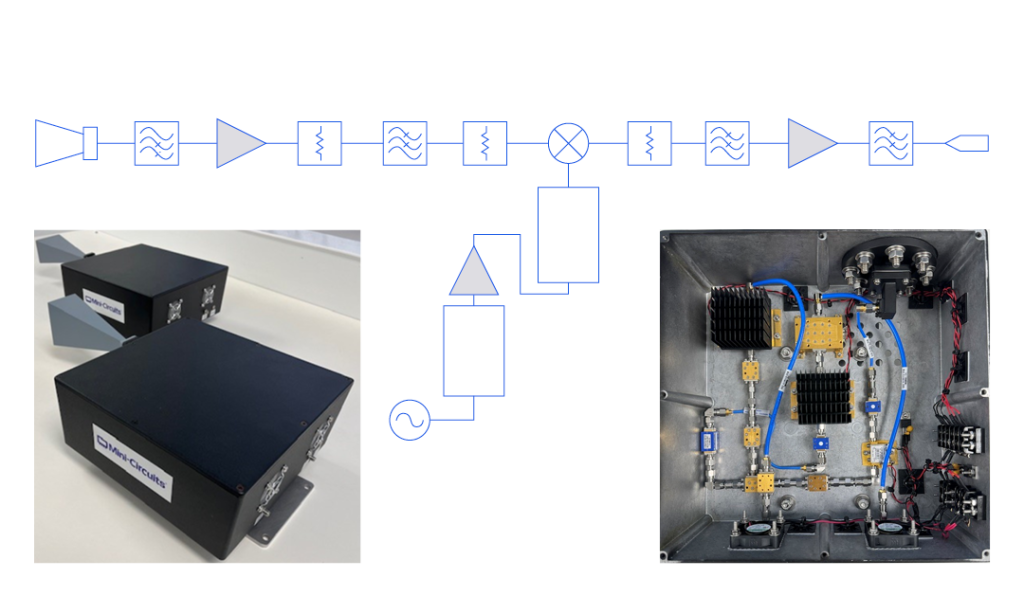
While much research has been devoted to exploring millimeter-wave bandwidths for high-data-rate wireless communications, much of the deployment of 5G to date has relied on frequencies in the sub-6 GHz (FR1) region of the spectrum. The channel capacity of the FR2 bands has been used in urban environments with high subscriber demand where infrastructure can be installed with sufficient density to compensate for the short range and poor penetration of high-frequency signals. Meanwhile, network operators still rely on lower-frequency signals for more ubiquitous coverage.
Similar desire for the data capacity and speed of millimeter-wave and sub-THz transmissions with broad network coverage and low power requirements of lower frequencies has spurred strong interest in the FR3 bands (7 to 24 GHz) as a possible “Goldilocks zone” for the next phases of 5G and 6G development.
Professor Ted Rappaport and his graduate research fellows of NYU WIRELESS in Brooklyn, New York are among the leading researchers exploring the propagation characteristics of 5G and 6G frequency bands under consideration for commercial use by the ITU and telecom industry. In 2022 Rappaport and his team visited Mini-Circuits’ facilities in Brooklyn, and Deer Park on Long Island as a test bed for their work to develop the first spatial statistical model for ultra-wideband signals above 100 GHz in a real-world factory environment.
Frequency Modulation Fundamentals
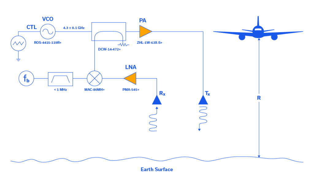
In the 1920s, many brilliant scientists applied themselves to the study of frequency modulation (FM). One of these scientists was a communications systems theorist who worked for AT&T named John Renshaw Carson. Carson performed a comprehensive analysis of FM in his 1922 paper which yielded the Carson bandwidth rule.1 Carson was so convinced that FM was not a suitable solution to the static found in AM transmission systems that he once remarked, “Static, like the poor, will always be with us.”2
Beginning in 1923, in Columbia University’s Marcellus Hartley Research Laboratory, in the basement of Philosophy Hall, a driven genius in electronic circuitry named Edwin Howard Armstrong set out to reduce static through the use of FM. After approximately 8 years of toil, Armstrong had a brainstorm and decided to challenge the assumption that the FM transmission bandwidth had to be narrow to keep noise low. After painstakingly designing this new FM system, with as many as 100 tubes spread over several tables in the laboratory, “[Armstrong] was able to prove that wideband FM made possible a drastic reduction of noise and static.”3 Armstrong was issued patent number US1941069A, which specifically addresses noise suppression in wideband FM, on December 26, 1933, along with three additional patents for FM that same day.
A Brief Overview of Phased Array Systems
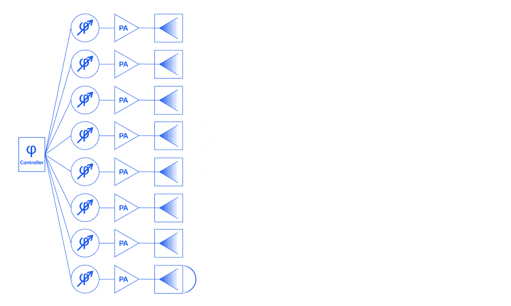
The concept of the phased array antenna system was first put into practice by German Physicist Ferdinand Braun and his assistants in the spring of 1905. In short, he and his assistants carefully controlled the excitation phase of each antenna in an array and determined that the combined effect exhibited significant directivity. In the nearly 12 decades since Braun first described the phased array antenna system, this technology has become commonplace in 4G/5G communications, electronic warfare, radar, nonlethal weaponry, and advanced imaging applications.1
This article begins with an overview of the evolution of phased array systems through history. A functional description of their basic operation in both analog and digital domains is provided, and a brief survey of common and emerging applications is given by way of example.
BOOST YOUR KNOWLEDGE: A COMPREHENSIVE GUIDE TO RF FREQUENCY MIXERS – TYPES AND APPLICATIONS EXPLAINED
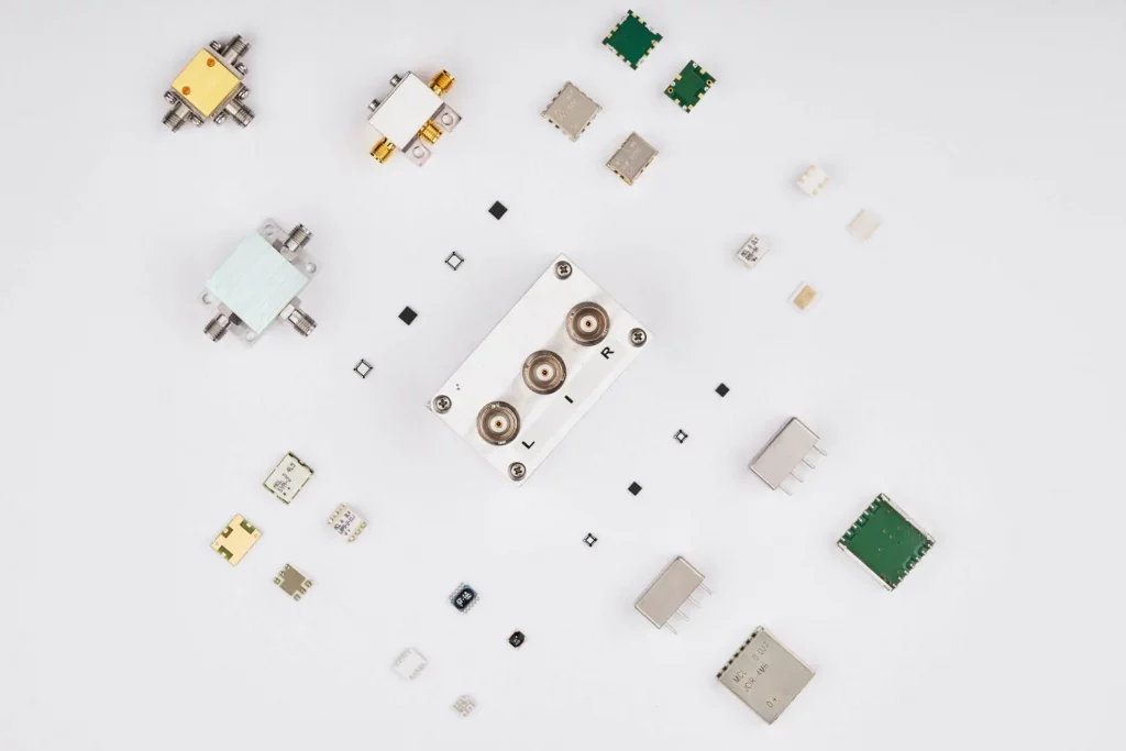
RF frequency mixers are electronic devices that are used to combine two or more RF signals to create a new signal with different frequency characteristics. These devices are used in a wide range of applications, including wireless communication systems, test and measurement equipment, and RF circuit design. RF frequency mixers can also be used to convert a signal from one frequency band to another, or to generate new signals for use in modulation or demodulation.
A Primer on Quadrature Amplitude Modulation (QAM)
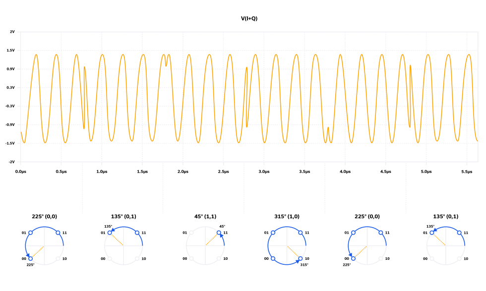
While other modulation schemes discussed in this blog series (pulse, frequency, amplitude, phase) date back to the early chapters of RF engineering history, quadrature amplitude modulation (QAM) was first described by C. R. Cahn in 19602 and evolved steadily over the next few decades. In the last 25 to 30 years, no modulation scheme has seen such widespread development and application as QAM. The technology has played a pivotal role in the industry’s ability to scale data speed and capacity with user demand by packing more data onto the carrier waveform and pushing a fixed channel bandwidth closer to Shannon’s limit. QAM modulation is used widely in cellular networks and backhaul, CATV networks and fixed wireless access points (802.11), and satellite communications to name a few. See Table 3 in Reference [3] for a more detailed list of applications.
In this article, we describe QAM using basic mathematics and illustrate how a QAM modulator operates. We introduce the concept of a constellation diagram and how it relates to the time domain plots for QAM modulation. A representative set of components is then utilized to design a functional QAM modulator by way of illustration. We conclude by describing how the QAM signal is demodulated at the receiver.
Every Block Covered: Cascaded P1dB and IP3 in a 26 GHz 5G Front-End
The goal of this article was to provide students and designers alike with a deeper understanding of the equations behind the cascading of P1dB and IP3 as the system expands to include multiple nonlinear components such as those utilized in the RF, frequency conversion and IF sections of a receiver chain. A 5G RF front end was presented for the 24.25 – 25.1 GHz portion of the 5G n258 frequency band comprised of all SMT parts. Calculated data for linearity parameters was presented for individual components in the signal chain as well as cascaded at each stage. The equations used to calculate those results were provided, and an examples were given showing how to calculate cascaded linearity parameters OP1dB and OIP3 from one stage to the next.
I&Q Mixers, Image Reject Down-Conversion & Single Sideband (SSB) Up-Conversion

In superheterodyne receivers and transmitters, frequency mixers perform the vital function of frequency translation. In down-converters, the incoming radio frequency (RF) signal is down-converted to an intermediate frequency (IF) to facilitate signal processing. Mixers are generally wideband devices, which convert unwanted image frequencies along with desired content to the same IF frequency, which is undesirable. Frequency mixers are often combined with quadrature hybrids to create image reject mixers (IRM), which we will explain herein.
Every Block Covered: Noise and Signal-to-Noise Ratio (SNR) in a 26 GHz 5G Front-End

The 24.25 to 27.5 GHz frequency range is also known as the “wider 26 GHz band” or 5G band n258. The Australian Communications and Media Authority (ACMA) “recognized that the wider 26 GHz millimeter wave (mmWave) band was at the forefront of the delivery of mmWave 5G wireless broadband services globally.”2 Consequently, in April 2021, a major portion of that spectrum was auctioned off to operators, predominantly in the 25.1 to 27.5 GHz frequency range.2 The 24.25 to 24.7 GHz band was identified for indoor use and the 24.7 to 25.1 GHz band for indoor/outdoor use.2 For the purposes of the RF front end in this application note, our focus will be on this lower, 24.25 to 25.1 GHz portion of the Australian 5G frequency range.
A Quick Guide to Mixer Topologies
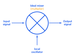
Real-world mixers come in many flavors. Mini-Circuits offers hundreds of unique mixer models representing six different circuit topologies. The good news is that this variety gives designers options for just about every application requirement. The problem, albeit a high-class problem, is that understanding the differences between mixer designs can complicate the component selection process.
This article will provide a broad overview of the different mixer topologies, including both balanced and unbalanced architectures. It should be noted that, in theory, any nonlinear device can be used to make a mixer, but Schottky diodes and Field Effect Transistors (FETs) are the most common. Mini-Circuits designs both diode- and FET-based mixers, but the topologies here will be presented using diode mixers for simplicity. However, the same principles can be applied to other technologies as well.
A Primer on RF Semiconductors (MMICs)
A Primer on RF Semiconductors (MMICs) Radhakrishna Setty, Technical Advisor Introduction Semiconductors are ubiquitous in modern society. In addition to microprocessors for computing technologies, they are used in practically every active wireless communications system including cell phone towers, cell phones, radars and satellites to name a few. Mini-Circuits designs and produces several semiconductor-based (MMIC) components […]


