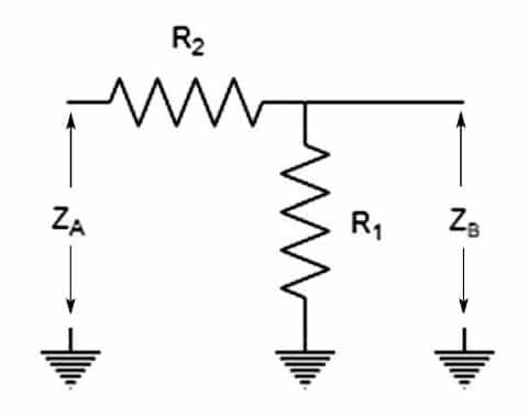

MCDI offers Mini-Circuits RF impedance matching pads designed to provide reliable broadband interfacing between 50 Ω and 75 Ω RF systems.
The portfolio includes surface-mount and connectorized coaxial matching pads with frequency coverage from DC to 3 GHz, making them suitable for CATV, broadband networks, satellite systems, laboratory testing and other applications where 50 Ω equipment must interface with a 75 Ω signal path.
Connectorized options include configurations using BNC, N-Type, SMA and F-type interfaces, allowing the matching device to provide both the required electrical impedance conversion and, in many applications, the required physical connector transition.
Mini-Circuits matching pads are designed for excellent impedance matching and flat attenuation across broad frequency ranges.
MCDI’s Application Engineering team in Israel can assist you in selecting the appropriate matching pad according to frequency range, 50 Ω and 75 Ω interfaces, connector configuration, attenuation, VSWR, RF power and application.
Hebrew & English Professional Support
Get a quote within hours or less
DDP & Ex-Works - your choice
Custom Adapters & Catalog modifications
Access to Mini-Circuits full portfolio
Mini-Circuits Quality & Reliability
Use the Impedance Matching Pad Catalog below to search and compare available Mini-Circuits products.
For complete electrical, mechanical, RF power and environmental specifications, always review the individual Mini-Circuits product datasheet.
Compare connectorized models according to:
Compare according to:
An RF impedance matching pad is a resistive network used to connect transmission systems having different characteristic impedances.
The Mini-Circuits matching-pad portfolio is primarily designed to interface:
50 Ω RF equipment
with:
75 Ω RF systems
50 Ω is widely used in RF, microwave, wireless and general-purpose test equipment.
75 Ω is widely used in applications such as:
Directly connecting a 50 Ω device to a 75 Ω transmission line creates an impedance mismatch.
That mismatch causes part of the RF signal to be reflected rather than transferred to the load.
A correctly designed impedance matching pad reduces these reflections by presenting the appropriate impedance to both sides of the connection.
When the impedance of the source, transmission line and load are different, RF energy can be reflected at the impedance discontinuity.
This can contribute to:
A matching pad provides a controlled transition between the two impedances.
This is particularly useful when 50 Ω laboratory equipment needs to test or operate with 75 Ω CATV or broadband devices.
A resistive impedance matching pad provides broadband matching by intentionally dissipating some RF signal power.
For an ideal minimum-loss resistive pad matching 50 Ω to 75 Ω, the theoretical minimum attenuation is approximately:
5.7 dB
This loss is not an unwanted defect in the device. It is a fundamental consequence of using a passive resistive network to simultaneously provide the required match between the two different impedances.
The key benefit is extremely broad frequency coverage.
Because the matching network is resistive rather than dependent on frequency-sensitive inductors, capacitors or transmission-line sections, a minimum-loss matching pad can operate from DC through a broad RF frequency range.
This makes matching pads especially useful in broadband test setups.
The most common resistive impedance-matching configuration is the minimum-loss L-pad.
It uses a carefully selected combination of series and shunt resistance to make:
while introducing the minimum theoretical loss required to provide that simultaneous impedance match.
For a conventional 50 Ω / 75 Ω minimum-loss pad, the expected attenuation is approximately 5.7 dB.
Individual Mini-Circuits products may have different nominal attenuation depending on their particular topology and application, so always refer to the product datasheet.
Surface-mount impedance matching pads are designed for PCB-level integration.
They can be useful when a circuit board contains both 50 Ω and 75 Ω sections or when a 75 Ω interface must be incorporated into predominantly 50 Ω RF electronics.
Typical applications include:
Important parameters include:
Mini-Circuits offers surface-mount 50 Ω / 75 Ω matching solutions with operation through 3 GHz.
Coaxial impedance matching pads provide a convenient way to connect existing 50 Ω and 75 Ω equipment without modifying either system.
Available configurations include connector combinations such as:
depending on model.
These products are particularly useful for:
The connectorized device can solve two problems simultaneously:
When selecting a matching pad, it is important to identify which side of the device is designed for 50 Ω and which side is designed for 75 Ω.
Do not select the product based only on connector gender.
For example, a connectorized matching pad may have:
50 Ω side: SMA Female
75 Ω side: F Male
or another combination depending on the specific model.
The product table and datasheet should clearly identify:
This is more useful than displaying only a generic connector description.
First confirm that the application actually requires conversion between:
50 Ω and 75 Ω
If both sides of the system use the same impedance, a matching pad is normally unnecessary.
The selected pad must maintain suitable attenuation flatness and VSWR throughout the complete operating-frequency range.
Mini-Circuits matching pads cover applications from DC to 3 GHz, depending on model.
Do not select a product only because its connectors fit physically. Verify its RF frequency specification as well.
Because the impedance conversion is performed using a resistive network, insertion loss is inherent.
For a conventional minimum-loss 50 Ω / 75 Ω pad, approximately 5.7 dB is expected.
Include this loss in the complete RF system power budget.
A broadband matching pad should ideally provide predictable attenuation over frequency.
Attenuation flatness indicates how much insertion loss varies across the operating band.
Good flatness is particularly useful in:
One of the primary reasons for using an impedance matching pad is to improve the match between 50 Ω and 75 Ω systems.
Review the specified VSWR or return loss on the relevant ports throughout the required frequency range.
Better matching means less reflected RF energy.
Select connectors that mate directly with the existing equipment where possible.
Connector families available across the Mini-Circuits matching-pad range include:
Eliminating unnecessary adapters can reduce:
Check both connector type and connector gender.
Available products include male and female configurations depending on model.
Selecting the correct combination can allow the matching pad to connect directly between two pieces of equipment.
The RF power applied to the matching pad is dissipated partly in its internal resistive network.
Always check the model’s specified power rating.
Do not assume that matching pads with identical impedance and frequency ranges have identical power-handling capability.
Choose surface mount when the impedance conversion will be integrated directly into a PCB or RF assembly.
Choose a connectorized matching pad when interfacing:
Production-test equipment
Both matching pads and impedance transformers can interface 50 Ω and 75 Ω systems, but they use fundamentally different approaches.
A matching pad:
For a minimum-loss 50 Ω / 75 Ω pad, the unavoidable attenuation is approximately 5.7 dB.
An impedance matching transformer:
For example, selected Mini-Circuits 50 Ω / 75 Ω matching transformers provide insertion loss well below that of a resistive minimum-loss pad.
Choose a matching pad when:
Consider a matching transformer when:
MCDI’s Application Engineers can help evaluate which approach is more appropriate.
CATV systems commonly use 75 Ω impedance, while much general-purpose RF laboratory equipment uses 50 Ω.
Matching pads allow engineers to connect equipment such as:
to 75 Ω CATV devices with improved impedance matching.
50 Ω / 75 Ω conversion may be required in broadband distribution and DOCSIS-related test environments where different equipment standards meet in the same signal path.
A broadband resistive matching pad provides predictable impedance conversion across a wide frequency range.
Most general-purpose RF instruments use 50 Ω interfaces.
When characterizing a 75 Ω device, directly connecting the instrument may introduce measurement error due to mismatch.
A suitable matching pad can provide the required impedance transition.
Matching pads can be integrated into production-test fixtures where 50 Ω automated test equipment needs to repeatedly measure 75 Ω products.
Their passive construction and broadband response make them convenient for repeatable test systems.
75 Ω interfaces are also commonly found in selected satellite receiver and distribution applications.
Matching devices can be used when those systems need to interface with conventional 50 Ω RF test or system components.
Some connectorized matching pads perform both impedance matching and connector conversion.
For example, a product may provide a transition between a 50 Ω SMA interface and a 75 Ω F-type interface.
This can eliminate the need for a separate adapter plus impedance-matching component.
Building an entire laboratory test system using only 75 Ω RF equipment can be difficult because much general-purpose test hardware is designed for 50 Ω systems.
Matching pads provide one method of incorporating 50 Ω test components into a 75 Ω signal path.
However, the attenuation introduced by the pads must be included in the measurement budget.
If a 50 Ω component is inserted between two 75 Ω system sections, matching may be required at both interfaces.
Two conventional minimum-loss pads can therefore introduce roughly 11.4 dB of matching-pad attenuation before including the insertion loss of the 50 Ω component itself.
For complex test systems, lower-loss impedance-transforming architectures or purpose-built 50 Ω / 75 Ω test solutions may be preferable.
Applications involving many channels or complex 50 Ω / 75 Ω transitions may benefit from an integrated test solution rather than multiple standalone matching pads.
MCDI and Mini-Circuits can support custom RF test systems incorporating functions such as:
This can reduce cabling complexity and provide a fully characterized test architecture for CATV, broadband and other mixed-impedance applications.
An RF impedance matching pad is a passive resistive network designed to connect RF systems having different characteristic impedances while reducing mismatch and signal reflections.
Mini-Circuits matching pads are primarily used for conversion between 50 Ω and 75 Ω systems.
50 Ω is widely used in general RF, microwave, wireless and test equipment.
75 Ω is widely used in applications such as CATV, broadband distribution, television and selected satellite-receiver systems.
Matching is required when equipment based on the two impedance standards needs to be interconnected with controlled RF performance.
A minimum-loss resistive matching pad must dissipate some signal power in order to present the correct impedance to both the 50 Ω and 75 Ω sides simultaneously.
For a conventional 50 Ω / 75 Ω minimum-loss network, the theoretical minimum attenuation is approximately 5.7 dB.
No.
For a resistive minimum-loss 50 Ω / 75 Ω matching pad, the attenuation is inherent to the impedance-conversion method.
The advantage is excellent broadband matching and operation down to DC.
A minimum-loss pad is a resistive matching network designed to provide impedance conversion with the lowest attenuation theoretically possible for the two impedances being matched.
Mini-Circuits currently offers 50 Ω / 75 Ω impedance matching pads with frequency coverage from DC to 3 GHz, depending on model.
Current connectorized matching-pad configurations include combinations using BNC, N-Type, SMA and F-type interfaces, depending on model.
Yes.
Mini-Circuits offers a surface-mount 50 Ω / 75 Ω matching-pad solution for PCB-level integration through 3 GHz.
A resistive matching pad provides very broadband matching, including operation down to DC, but introduces inherent attenuation.
A transformer can provide much lower insertion loss but its impedance transformation and bandwidth are frequency dependent.
Neither is universally better.
Use a matching pad when wide bandwidth, DC operation and predictable broadband matching are important and the insertion loss is acceptable.
Consider a transformer when preserving signal power is more important and the required operating band is compatible with the transformer.
Yes.
Selected connectorized products combine impedance transformation with connector conversion, for example between a 50 Ω SMA interface and a 75 Ω F-type interface.
Yes.
CATV testing is one of the principal applications because CATV equipment typically uses 75 Ω interfaces while much general-purpose RF test equipment uses 50 Ω.
Approximately, yes, for two similar minimum-loss pads.
Two conventional 50 Ω / 75 Ω minimum-loss pads would introduce roughly 11.4 dB of matching-pad attenuation before considering the loss of the equipment between them.
Yes.
MCDI’s Application Engineering team in Israel can help determine whether a resistive matching pad, matching transformer or another impedance-conversion technique is best suited to your bandwidth, insertion-loss, DC and connector requirements.
MCDI is Mini-Circuits’ exclusive representative and distributor in Israel, providing Israeli engineers and purchasing teams with access to Mini-Circuits RF components together with local technical, commercial and logistical support.
Local Application Engineering
Selecting the correct matching approach involves more than choosing 50 Ω and 75 Ω.
MCDI’s Application Engineers can help evaluate:
and determine whether a matching pad or another impedance-transforming solution is most appropriate.
Technical Support in Hebrew and English
Discuss your RF requirements directly with an Israel-based engineering team familiar with Mini-Circuits RF products and test solutions.
Complete Mixed-Impedance Support
MCDI can assist with related 50 Ω / 75 Ω Mini-Circuits products including:
Product Selection Assistance
If you know the 50 Ω and 75 Ω interfaces but are unsure whether a resistive matching pad or lower-loss transformer is appropriate, send MCDI your application requirements.
Support from Selection Through Delivery
MCDI supports customers in Israel from product selection and quotation through ordering, logistics and post-sales technical assistance.




Before you leave, you should know that MCDI’s professional team of Application Engineers will be delighted to assist you in sourcing the right component. Just fill the form and we will be back to you shortly.