
MCDI offers a broad selection of Mini-Circuits RF, microwave and millimeter-wave equalizers designed for gain flattening and frequency-dependent loss compensation in wideband RF systems.
The portfolio includes fixed-slope equalizers and voltage-variable equalizers, with surface-mount, connectorized and bare-die solutions for applications ranging from communications and satellite systems to RF test equipment, radar and broadband instrumentation.
Mini-Circuits equalizer solutions cover frequencies from DC to 45 GHz, with multiple attenuation slopes and both 50 Ω and selected 75 Ω configurations.
RF equalizers are particularly useful where amplifiers, cables or complete RF signal chains exhibit progressively greater loss or reduced gain as frequency increases. By intentionally providing greater attenuation at lower frequencies and less attenuation at higher frequencies, an equalizer can help produce a flatter overall system response.
MCDI’s Application Engineering team in Israel can assist you in selecting the appropriate equalizer according to frequency range, required slope, insertion loss, return loss, RF power, linearity, impedance, package and control requirements.
Hebrew & English Professional Support
Get a quote within hours or less
DDP & Ex-Works - your choice
Custom Adapters & Catalog modifications
Access to Mini-Circuits full portfolio
Mini-Circuits Quality & Reliability
Use the RF Equalizer Catalog below to search and compare Mini-Circuits models according to your application requirements.
For complete electrical, mechanical, environmental and absolute maximum specifications, always review the individual Mini-Circuits product datasheet.
Search and filter according to:
Search and compare models according to:
An RF attenuator and an RF equalizer both reduce signal amplitude, but they are designed for different purposes.
A conventional attenuator is generally intended to provide approximately the same attenuation across its specified frequency range.
For example, a 10 dB fixed attenuator is designed to reduce signal power by approximately 10 dB throughout its operating band.
An equalizer intentionally provides different attenuation at different frequencies.
For example, it may provide greater attenuation at low frequencies and progressively less attenuation toward the high end of the band.
This frequency-dependent attenuation makes the equalizer useful for correcting system gain slope.
Many RF components do not have perfectly flat amplitude response over frequency.
For example:
In a narrowband system, these variations may have relatively little effect.
In a broadband system, however, gain variation across the operating band can degrade signal quality, measurement accuracy and overall system performance.
An RF equalizer introduces a complementary frequency response so that the combined system becomes flatter.
A fixed-slope equalizer provides a predetermined attenuation-versus-frequency characteristic.
It is generally used when the frequency response that needs correction is predictable and does not change significantly during operation.
For example, if an RF amplifier exhibits progressively decreasing gain toward higher frequencies, a suitable fixed equalizer can introduce greater attenuation at the lower end of the band and less attenuation at the upper end.
The resulting combined amplifier-plus-equalizer response can be significantly flatter.
Mini-Circuits offers fixed-slope equalizers with:
Fixed equalizers are attractive because they require no DC supply or control signal.
A voltage-variable equalizer allows the attenuation slope to be adjusted electronically.
Rather than being limited to one fixed compensation characteristic, the amount of equalization can be controlled according to changing system conditions.
This can be useful when:
Mini-Circuits voltage-variable equalizers provide adjustable slope under analog voltage control.
Important parameters include:
Selected models are available for both 50 Ω and 75 Ω systems.
Surface-mount RF equalizers are suited to integration directly into RF and microwave PCBs.
Benefits can include:
Mini-Circuits’ EQY-series includes compact MMIC equalizers covering multiple bandwidths and slopes, including products operating through 45 GHz.
Connectorized equalizers provide convenient integration into laboratory setups, complete RF systems and test equipment without requiring PCB-level implementation.
They can be useful for:
Connectorized equalizers allow engineers to insert frequency-dependent compensation directly into an existing coaxial signal path.
Selected Mini-Circuits fixed equalizers are also available in bare-die format for chip-and-wire and hybrid microwave assemblies.
Bare-die equalizers can be useful where:
MCDI can assist with identifying packaged and bare-die versions of suitable equalizers.
Equalizer slope describes the difference in attenuation between the lower and upper ends of the specified frequency range.
A typical negative-loss-slope equalizer has:
For example, consider a broadband amplifier whose gain falls by approximately 6 dB between the lower and upper ends of its operating range.
A suitably selected equalizer with approximately complementary frequency-dependent attenuation may reduce low-frequency signal level more than high-frequency signal level.
The combination can therefore produce a much flatter overall response.
The correct slope should be selected from measured or specified system gain-versus-frequency data rather than from the nominal bandwidth alone.
The equalizer must cover the complete frequency band over which gain flattening is required.
Mini-Circuits fixed equalizer families include products designed for bandwidths extending through frequencies such as:
depending on the model.
Always verify equalizer performance across the actual operating band.
The required equalizer slope should complement the gain variation of the RF system.
If the system loses approximately 5 dB more gain at its upper frequency than at its lower frequency, an equalizer with a suitable complementary response may help flatten the overall gain.
However, the optimum slope should be determined using actual system data whenever possible.
Consider:
Even at the end of the band where the equalizer provides its lowest attenuation, some insertion loss generally remains.
This loss must be included in the system gain budget.
When comparing equalizers with similar slopes, high-frequency insertion loss may therefore become an important selection parameter.
A perfect equalizer would follow exactly the desired attenuation-versus-frequency curve.
In practice, there may be some deviation from an ideal linear slope.
This can affect the final gain ripple after equalization.
For demanding wideband systems, evaluate the actual frequency-response data rather than relying only on the nominal slope value.
The equalizer forms part of the RF transmission path and should maintain suitable impedance matching across the operating range.
Poor matching may:
Review return loss or VSWR throughout the required frequency band.
For fixed equalizers, confirm that the maximum RF input power is appropriate for the signal level in your system.
Do not assume that equalizers with similar frequency and slope specifications have identical power-handling capability.
Always refer to the individual product datasheet.
For voltage-variable equalizers, parameters such as IP3 and P1dB may be important.
These specifications help determine how the equalizer behaves when handling higher signal levels or multiple RF signals.
High-linearity performance may be particularly important in:
Voltage-variable equalizers require an analog control voltage to adjust their attenuation slope.
Confirm:
before integrating the device into the system.
Most RF, microwave, radar and test systems use 50 Ω impedance.
Selected Mini-Circuits voltage-variable equalizers are also offered in 75 Ω versions for broadband and distribution applications.
The equalizer impedance should match the surrounding signal chain.
Choose a fixed-slope equalizer when:
Choose a voltage-variable equalizer when:
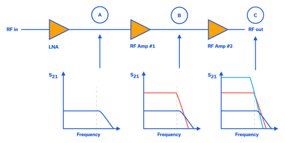
Amplifier gain often changes across frequency.
A fixed equalizer can be cascaded with an amplifier to compensate for its negative gain slope and produce a flatter combined response.
Coaxial cable insertion loss normally increases as frequency increases.
An equalizer can provide a complementary response, helping compensate for this frequency-dependent cable loss.
Voltage-variable equalizers are particularly useful when different cable lengths or changing conditions require adjustable compensation.
Modern wideband modulation formats can be sensitive to amplitude variation across the occupied bandwidth.
Equalization can help improve the flatness of broadband RF signal chains used in advanced wireless transmitters, receivers and test systems.
Wideband SATCOM signal chains can contain amplifiers, cables, filters and other components whose combined gain response changes with frequency.
RF equalizers can help compensate for this accumulated system slope.
Broadband radar transmit and receive chains may require amplitude equalization to maintain predictable gain across the operating frequency range.
Equalizers can be used in laboratory and automated test setups to compensate for predictable frequency-dependent loss in:
Receiver gain can vary significantly across a wide operating band.
An equalizer placed at an appropriate point in the chain can improve overall gain flatness while allowing the designer to balance noise figure, gain and linearity requirements.
Frequency-dependent gain or loss in a transmitter signal chain can produce uneven output amplitude across frequency.
A suitable equalizer can help compensate for this variation before the signal reaches subsequent amplifier stages.
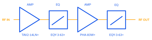
Equalizers and amplifiers are frequently used together.
Consider an amplifier whose gain decreases as frequency increases.
The equalizer can provide greater attenuation where amplifier gain is highest and less attenuation where amplifier gain is lowest.
The combined result can therefore have substantially flatter gain than the amplifier alone.
Equalizer placement must still consider:
MCDI’s Application Engineers can assist with selecting both the amplifier and equalizer for a complete RF signal-chain requirement.
An RF equalizer is a component designed to introduce a controlled frequency-dependent attenuation characteristic into an RF signal path.
It is commonly used to compensate for frequency-dependent gain or loss elsewhere in the system.
A typical slope equalizer provides greater attenuation at lower frequencies and progressively less attenuation as frequency increases.
When cascaded with a signal chain whose gain decreases with frequency, the combined response can become flatter.
Equalizer slope is the difference in attenuation between defined lower and upper frequencies.
It describes the amount of frequency-dependent amplitude correction provided by the equalizer.
A fixed-slope equalizer has a predetermined attenuation-versus-frequency response that does not require electronic adjustment or DC control.
A voltage-variable equalizer allows its attenuation slope to be adjusted using a control voltage.
This is useful when the required compensation changes according to operating conditions or system configuration.
A conventional attenuator is generally designed to provide approximately constant attenuation across frequency.
An equalizer intentionally provides different attenuation at different frequencies in order to compensate for frequency-dependent system response.
Yes.
Because coaxial cable loss generally increases with frequency, a suitably selected equalizer can provide greater attenuation at lower frequencies and less attenuation at higher frequencies, helping flatten the overall cable-plus-equalizer response.
Yes.
Equalizers are frequently used with broadband amplifiers whose gain decreases with frequency.
A complementary equalizer response can improve the combined gain flatness.
The optimum position depends on the complete system requirements.
Placing an equalizer before or after an amplifier can have different effects on system gain, noise figure, compression and linearity.
For demanding applications, the complete cascaded signal chain should be evaluated.
A passive fixed equalizer does not create RF gain.
Instead, it reduces lower-frequency signal levels more than higher-frequency levels.
When its response is viewed relative to frequency, this can appear as a positive gain slope, but the component itself remains lossy.
Mini-Circuits currently offers fixed and voltage-variable RF equalizer solutions covering applications from DC through 45 GHz, depending on the individual model.
Yes. Mini-Circuits offers fixed-slope MMIC equalizers covering DC to 45 GHz, with multiple slope values and packaged and bare-die configurations.
Yes. Mini-Circuits offers selected connectorized fixed-slope equalizers for direct integration into coaxial RF systems and test setups.
Yes. Selected Mini-Circuits voltage-variable equalizers are available for 75 Ω systems.
Yes. Provide MCDI with your operating frequency range and, ideally, measured or specified gain-versus-frequency data for your existing signal chain.
MCDI is Mini-Circuits’ exclusive representative and distributor in Israel, providing Israeli engineers and purchasing teams with access to Mini-Circuits RF, microwave and millimeter-wave products together with local technical, commercial and logistical support.
Local Application Engineering
Equalizer selection often requires comparing measured gain-versus-frequency data with available attenuation slopes.
MCDI’s Application Engineers can help evaluate:
and identify suitable Mini-Circuits equalizer options.
Technical Support in Hebrew and English
Discuss your RF requirements directly with an Israel-based engineering team familiar with Mini-Circuits RF components and systems.
Complete Signal-Chain Support
MCDI can assist not only with the equalizer itself but also with related RF components such as:
This can help when equalization needs to be considered as part of the complete system rather than as an isolated component.
Special & Custom Solutions
If a standard equalizer does not provide the required frequency response or mechanical configuration, contact MCDI to discuss available special or custom Mini-Circuits solutions.
Support from Selection Through Delivery
MCDI supports customers in Israel from product selection and quotation through ordering, logistics and post-sales technical assistance.




Before you leave, you should know that MCDI’s professional team of Application Engineers will be delighted to assist you in sourcing the right component. Just fill the form and we will be back to you shortly.