A Quick Guide to Mixer Topologies
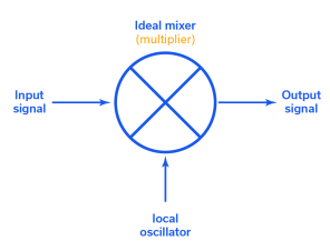
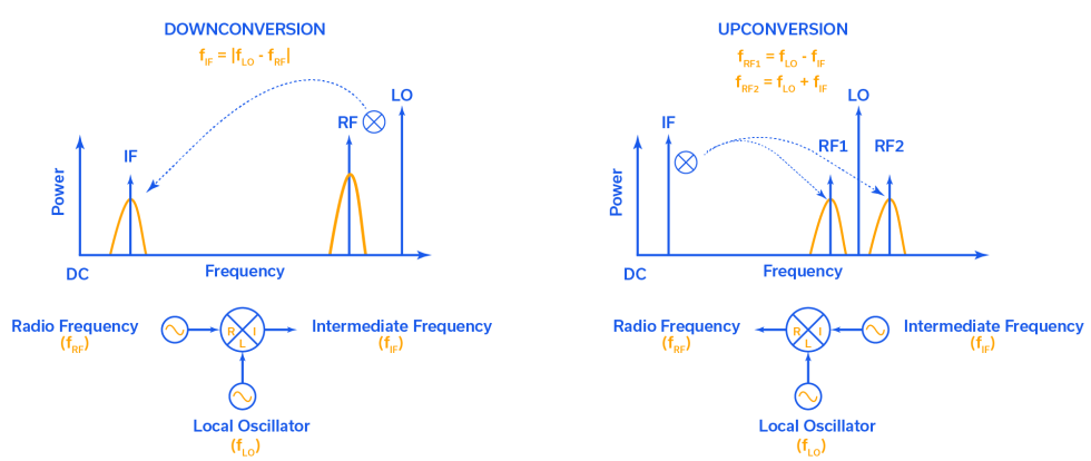
RF / microwave mixers live at the center of every RF transceiver system, and are the essential element to converting baseband signal into RF on the transmit side and vice versa on the receive side. All mixers have three ports, one for intermediate frequency or baseband (IF), one for the local oscillator or carrier (LO) and another for the radio frequency signal (RF). In the transmit path, IF and LO inputs combine into an RF output; on the receive side, RF and LO combine and down convert to IF output. In both cases, the two input signals are “mixed” to create two new signals at the output – the sum frequency (LO +RF) and the difference frequency (LO – RF). One of these mixing products is suppressed, depending on whether up- or down-conversion is desired. The basic block diagram for an RF mixer is shown in Figure 1.
Real-world mixers come in many flavors. Mini-Circuits offers hundreds of unique mixer models representing six different circuit topologies. The good news is that this variety gives designers options for just about every application requirement. The problem, albeit a high-class problem, is that understanding the differences between mixer designs can complicate the component selection process.
This article will provide a broad overview of the different mixer topologies, including both balanced and unbalanced architectures. It should be noted that, in theory, any nonlinear device can be used to make a mixer, but Schottky diodes and Field Effect Transistors (FETs) are the most common. Mini-Circuits designs both diode- and FET-based mixers, but the topologies here will be presented using diode mixers for simplicity. However, the same principles can be applied to other technologies as well.
Unbalanced (Single Diode) Mixers
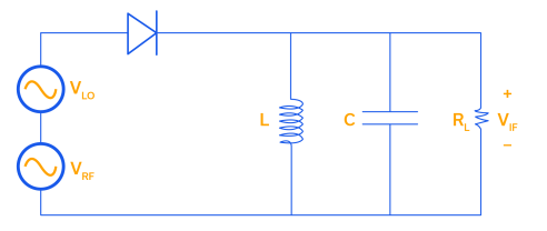
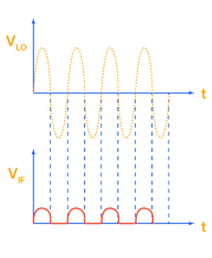
A single diode, or unbalanced, mixer is the simplest and oldest mixer topology. A single diode mixer is fundamentally a two-port device, with the RF and LO combined and fed into the diode, and the IF delivered on the other side of the diode. The schematic and time domain response of this topology is shown in Figure 2.
Figure 2: Unbalanced / single-diode mixer schematic and time domain response.
One of the limitations of the unbalanced mixer is that in addition to the desired IF frequency (sum or difference), the output frequency spectrum also includes RF and LO signal content, and therefore requires a narrowband IF filter to reject the RF and LO frequency components of the output signal. The output RLC tank in Figure 2 is tuned to match the IF frequency. This means the single device mixer has a rather narrow IF bandwidth because it has no port isolation. Single diode mixers are used in economical receiver front-ends, and bandpass filters can be used at the input and output to separate the LO, RF, and IF signals. They can, however, be problematic if the RF and LO frequencies overlap and the filtering requirement becomes too difficult.
Advantages and Disadvantages of the Unbalanced Diode Mixer
Advantages
- Very useful in at millimeter wave band
- Economical
- Lowest LO requirement
Disadvantages
- No isolation
- Filtering results in narrow operation band
- No rejection of LO AM noise or intermodulation products
Single Balanced Mixers
Single balanced mixers can remove either the LO or RF content from the IF output without the use of filters by using two diodes and a 180° hybrid coupler as a balun. Early wideband receivers used a 90° hybrid combiner, which still separated the RF and LO, but the isolation was dependent on how well the diodes were impedance matched. The 180° hybrid coupler solved this problem. [Source 09-21] This technique isolates the RF and LO ports and reduces unwanted intermodulation products. The RF and LO signals are applied to the sum and delta ports of the hybrid, the two outputs of which each feed one diode, one facing toward the hybrid and the other away. The outer ends of both diodes are tied together as the IF output. Depending on the configuration, only the LO or RF will appear with the IF (the input signal applied to the 180° port of the hybrid will be balanced and not appear at the IF output). The block diagram of a single balanced mixer is shown in Figure 3.

An example schematic of a single-balanced mixer is shown below in Figure 4 with the 180° hybrid at the RF and LO input ports and a low pass filter (LPF) at the IF output port (L1, C2, and C3 network). The LO is balanced and drives the on/off action of the Schottky diodes. The RF signal is suppressed from the IF output by a capacitor to ground (C1) as well as a dedicated low-pass filter (LPF). At higher LO powers, the diodes can self-bias, causing unacceptable conversion loss and isolation. To avoid this, RF chokes (RFC) are shunted to ground between the coupler and the diodes.

Of the balanced mixers, single-balanced mixers require the least amount of LO power. The LO or RF rejection at the IF output is typically between 20 and 30 dB.
Advantages and Disadvantages of the Single Balanced Mixer Topology
Advantages
- Requires least LO of the balanced types
- Suppresses AM noise from LO (unbalanced does not)
Disadvantages
- Only isolation of RF or LO without filtering
- Filtering results in narrow operation band operation
- Requires more LO than unbalanced
- Less linear than double-balanced
- More conversion loss than double-balanced
Double Balanced Mixers
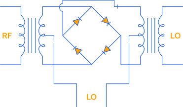
The double balanced mixer topology has four diodes in a ring or star configuration along with two baluns (one each for the RF and LO), and provides rejection of both the LO and RF content at the IF output. This means all ports are inherently isolated from each other without the need for filtering. This is due to the combined properties of the ring diode circuit and the wideband baluns.
Compared to single-balanced mixers, double-balanced diode mixers have more linearity and less spurious emissions. They also tend to have better conversion efficiency and can achieve broader bandwidths since no filtering is required at the IF port. However, this mixer architecture requires a higher LO drive level, and the ports are highly sensitive to reactive terminations.
The ideal application for a double-balanced mixer is a lower-cost application where moderate LO power is available and the RF and IF frequencies do not overlap.

An example double-balanced mixer schematic for the block diagram in Figure 6 is shown in Figure 7. The IF signal is tapped off of both the LO and RF baluns. Using separate baluns for the RF and LO ports provides isolation between the RF and LO ports, reducing the level of intermodulation products compared to that of an unbalanced mixer.
Advantages and Disadvantages of the Double Balanced Diode Mixer
Advantages
- Inherent isolation of both RF and LO
- More linear than single-balanced
- Less spurs than single-balanced
- Broadband device (no filtering needed)
Disadvantages
- Requires more LO than single-balanced
- Ports sensitive to reactive terminations
Triple-Balanced Mixers
The triple-balanced mixer topology further improves upon the linearity of double-balanced designs, but also requires yet higher LO power level for operation. The triple-balanced mixer uses eight diodes and several baluns, and is sometimes called “doubly double balanced” because it consists of two double balanced mixers in push-pull configuration.
A block diagram for a triple balanced mixer is shown in Figure 8 and a more detailed schematic is shown in Figure 9. Two hybrids are required for both the RF and LO ports, as well as a single hybrid coupler for the IF port.
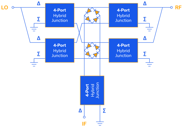
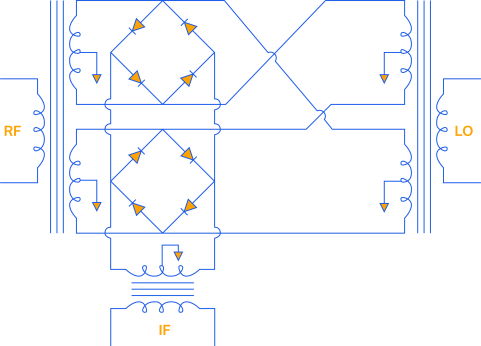
This architecture provides better isolation and suppression of spurious and intermodulation products than the double balanced mixer topology. Triple balanced mixers also have a wide IF bandwidth. Triple-balanced mixers are ideal for applications where wideband signals need to be translated from one frequency range to another with minimal intermodulation products.
Advantages and Disadvantages of the Triple Balanced Mixer Topology
Advantages
- Better linearity than double-balanced
- Ideal for wide band applications
- Ideal for RF/IF overlap situations
Disadvantages
- Requires more LO than double-balanced
Summary Comparison of Unbalanced and Balanced Mixer Topologies
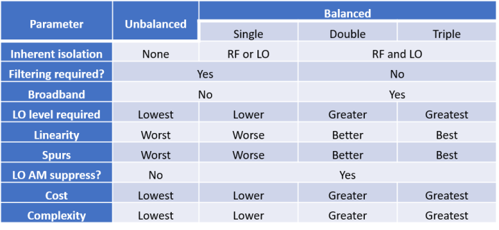
The table below provides a broad comparison of all the balanced mixer topologies presented so far.
IQ mixers
The “I” in IQ stands for “in-phase” and the “Q” stands for “quadrature.” IQ mixers allow the two frequency sidebands to be handled separately using quadrature modulation where phase becomes a variable in data transmission. Quadrature modulation ultimately doubles the information content in a double-sideband transmission since each sideband can contain different information. The block diagram of an IQ mixer is shown in Figure 10.
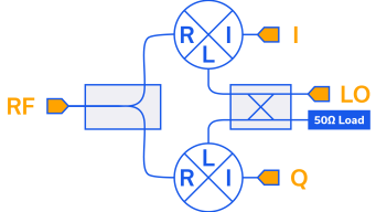
An IQ mixer comprises two mixers, each with the LO phase shifted by 90° from the other with a hybrid coupler. One mixer handles the in-phase LO component, and the other handles the quadrature component. The I and Q output signals are baseband signals combined into an RF signal for transmission. At the receiver, the process is reversed with the RF signal separated back into 1 and Q baseband channels. Any of the unbalanced or balanced mixer topologies discussed here can be used to create the IQ mixer configuration.
Mini-Circuits uses the terminology modulators/demodulators to classify IQ mixer products, which can be found under the “Modulators/Demodulators” section of the website.
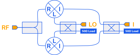
An IR/SSB mixer is an IQ mixer with an additional hybrid coupler that is fed by the I and Q ports. The purpose of this additional coupler is to cancel one of the sidebands’ ports with a terminated load. The remaining coupler port is used as the output (IR / receive) or input (SSB / transmit) of the mixer. Any of the unbalanced or balanced mixer topologies discussed above can be used to create an IR / SSB mixer configuration.
Summary
Mini-Circuits offers one of the industry’s widest selection of RF and microwave mixers comprising all of the topologies discussed in this article. You should now be better equipped to navigate our catalog and find the right model for your requirements.


