

A Brief Overview of Phased Array Systems

The concept of the phased array antenna system was first put into practice by German Physicist Ferdinand Braun and his assistants in the spring of 1905. In short, he and his assistants carefully controlled the excitation phase of each antenna in an array and determined that the combined effect exhibited significant directivity. In the nearly 12 decades since Braun first described the phased array antenna system, this technology has become commonplace in 4G/5G communications, electronic warfare, radar, nonlethal weaponry, and advanced imaging applications.1
This article begins with an overview of the evolution of phased array systems through history. A functional description of their basic operation in both analog and digital domains is provided, and a brief survey of common and emerging applications is given by way of example.
The Evolution of Phased Arrays
The first phased array beamforming antenna system demonstrated by Ferdinand Braun and his assistants in 1905 required cumbersome electromechanical hardware (i.e. changeover switches) to change the relative phase of the spark-gap-generated transmission appearing at each of the three antennas. Due to the primitive nature of the electromechanical components at the time, antenna arrays were mechanically scanned well into the 1930s.
Electronically scanned phased arrays began to appear in the late 1930s, likely with more modern electromechanical elements (relays, solenoids) performing the switching/phase-changing operations. This type of phased array, the Circularly Disposed Antenna Array (CDAA), was one of the largest to be designed and manufactured and was produced from the late 1930s through the 1960s. CDAAs operated in essentially the HF frequency band (3 to 30 MHz) and were used for direction finding (DF) and intelligence gathering. The US Navy AN/FRD-10 was a CDAA for which the circular arrangement measured over 850 feet in diameter and the operational range was estimated at 3200 nautical miles.9 The AN/FRD-10 could detect HF signals between 2 and 32 MHz.9
Phased arrays have evolved from these gigantic, passive, relatively low-frequency CDAA structures of yesteryear to the sleek, integrated, digital, tower top 5G beamformers and airborne, active electronically scanned array (AESA) radars, due to the many technological advancements that have taken place over the past eight decades. In recent decades, there’s been a heavy emphasis placed on reducing SWaP-C (Size, Weight, Power and Cost) for defense systems in particular. Advances in materials science and manufacturing techniques have played a major role, but most of the critical innovation and miniaturization has been achieved through the maturation of solid-state components, or semiconductor technology.
Modern day phased arrays utilize a multitude of highly integrated silicon, GaAs and GaN semiconductor devices to perform as phase shifters, power amplifiers, LNAs, attenuators, limiters and switches. These semiconductor devices are combined into a transmit/receive (T/R) module which interfaces with each antenna element. A simplified block diagram of such a T/R module is shown in Figure 1. Phased arrays have also become so highly integrated that some of these functions are combined on a single wafer. It is not surprising to find the entire T/R functionality for many array elements integrated on a single semiconductor wafer.

The Digital Revolution in Phased Arrays
All the typical analog functions are shown in Figure 1 such as the switches, limiter, LNA, HPA, phase shifter and variable attenuator. The phase shifter and variable attenuator functions can be performed digitally as illustrated by the topology shown in Figure 2. The common leg amplifier from Figure 1 is placed in both the HPA and LNA paths. The T/R switch and limiter remain part of the design, heterodyned down to IF before the ADC and upconverted after the DAC.

In analog beamforming, adjustments are made to a discrete phase shifter or variable attenuator, either digitally or with an analog voltage. In fully digital beamforming, each Tx antenna element receives its individual, upconverted digital stream which originates from the digital beamforming processor replete with phase shifts and amplitude corrections. On the Rx side, digital phase and amplitude adjustments are made after the IF signal undergoes analog-to-digital conversion. Digital beamforming affords maximum flexibility in handling the phased array’s time-frequency-space resources and in generating any number of superimposed beams to be able to track multiple threats while searching for others.10
The simplified block diagram of Figure 2 does not consider the processing power required for digital beamforming. Arrays can have hundreds and often thousands of elements. Steering multiple beams and adapting to the operational environment in real time as well as handling multipath and fading effects requires tremendous digital processing resources. Data traffic for a phased array can easily reach many Terabits per second. This magnitude of data processing requires high-speed field programmable gate arrays (FPGAs) with millions of digital logic cells. The current state of the art stands at 18.5 million, and the FPGA is referred to by AMD as an Adaptive System-on-a-Chip (SoC).11
As shown in Figure 2, in digital beamforming, the ADC and DAC are on board the T/R module. Often these must be fast components, capable of converting to/from baseband from/to IF. Current sample hardware exists in the 16 GHz range for 12-bit ADCs and near 20 GHz for a 14-bit DAC.
Other Phased Array Applications
Smart beamforming antennas for telecommunications and land, sea and airborne radars are two common applications of phased arrays. One of the newer and less obvious is a directed energy weapon known as the Active Denial System (ADS). The ADS system that most are familiar with is integrated into a military Humvee with the phased array antenna, which is capable of rotating 360⁰, mounted to the top of the vehicle. The system delivers a high-power dose of 94-95 GHz energy which begins to heat the top 1/64 of an inch (0.016 in.) of an enemy combatant’s skin, causing a non-lethal burning sensation within 2 seconds causing those in its path to flee. But it takes an entire Humvee to power the ADS, and it’s not that agile or mobile.
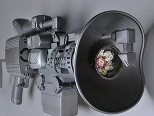
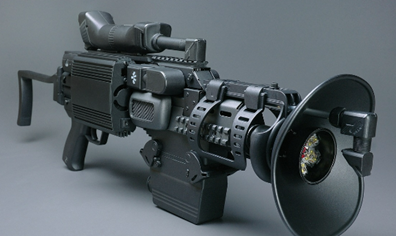
Fast forward a few years and the same technology may realize something of a science fiction device: a real heat ray gun. The prop in Figure 3 was used in the TV series Arrow13 and billed as a directed energy rifle. While it appeared to powerfully discharge on the TV show, the concept of a handheld ray gun was chosen because it was large enough to hold sufficient battery energy (two cordless drill battery packs) and had the appearance of a hybrid phased array/reflector arrangement on the front, which could afford both high directivity and some measure of beam steering.
Figure 3: Directed energy rifle prop used in the TV series Arrow.13
The measured pain threshold in 10 people for 3-second pulses at 94 GHz was 37.5 kJ m−2, which produced a peak skin temperature rise of approximately 10⁰C (18⁰C).
Narrow Pulse Modulation and UWB Radar Phased Arrays
One application of ultra-wideband (UWB) technology utilizes sub ns pulses and broad bandwidths to perform imaging that can penetrate surfaces. Due to the proliferation of UWB applications, the FCC has allocated the 3.1 to 10.6 GHz in 500 MHz channels to UWB, with tight radiation limits in light of the fact that the emissions are spread over such a broad bandwidth. Commercial UWB systems are low power and low cost. Additionally, because of the excellent timing constraints that can be placed upon narrow pulses and their returns (echos), UWB systems are highly precise.
It is not uncommon for a UWB system to utilize a pulse of approximately 100 ps and a PRF of anywhere from 1 to 50 MHz. The theoretical limit on these systems’ range is due to the transmitted power constraints. Military UWB phased array radars are not constrained to those same commercial standards in times of need, so the nature of military applications is slightly different. High-voltage GaN and SiC switching devices could contribute the power necessary to extend the range of military UWB systems. No longer must the system be within tens of meters. Standoff distances of hundreds of meters would be possible, with exceedingly rapid scanning and multiple beam performance. Excellent foliage- and ground-penetrating radars could be built. “See-through-the-wall” precision radar imaging could track many individuals at once, detecting vital signs and vocal cord vibrations to instantaneously determine who the speaker is and what they are communicating.
The Final Phase
We began by describing the achievements of Ferdinand Braun, such as his phased array and his loosely-coupled transformer for driving the antenna. These contributions enabled other wireless pioneers to communicate over greater distances and with less interference than was otherwise possible. We described briefly how the technology transitioned from clumsy CDAAs to modern day digital beamforming arrays in more recent history. Next we discussed T/R modules, showing the discrete components that comprise a T/R module as well as a discussion of their high level of integration. The digital beamformer phased array of Figure 2 was discussed and it was determined that, although the capability is excellent, the digital solution often requires vast digital resources. States of the art in FPGA complexity and ADC and DAC speed were also determined. We concluded a survey of applications of phased arrays that have unique capabilities, such as a 94 GHz vehicle-mounted non-lethal deterrence system and concept for a portable heat ray gun. We also envisioned what the capabilities of a high-power, UWB military imaging phased array might be in practice.
Mini-Circuits products are frequently used on the periphery of antenna arrays similar to those described herein for signal processing between the antenna array and transceiver chain. LTCC filters, balun transformers and integrated balun-filters have become especially popular for these uses due to their small size, low cost and repeatability.
References
- Karl Ferdinand Braun – Wikipedia
- Karl Ferdinand Braun – Nobel Lecture (nobelprize.org)
- Ferdinand Braun (nndb.com)
- Biography of Karl Ferdinand Braun | nitum (wordpress.com)
- Spark-gap transmitter – Wikipedia
- Wireless: From Marconi¬タルs Black-Box to the Audion (monoskop.org)
- File:British patent 22,020-Karl Ferdinand Braun-filed 3 November 1899-fig. 2.png – Wikipedia
- History of smart antennas – Wikipedia
- AN/FRD-10 – Wikipedia
- Optical_Interconnects_for_Future_Advanced_Antenna_Systems-Architectures_Requirements_and_Technologies 1-22-2022.pdf (hubspotusercontent-na1.net)
- With 18.5 million logic cells, AMD’s Versal VP1902 Premium Adaptive SoC becomes “World’s Largest FPGA” – EEJournal
- Advances in GaN Devices and Circuits at Higher mm-Wave Frequencies – ScienceDirect
- Directed Energy Rifle – ARROW (propology.ca)
- Time-temperature Thresholds and Safety Factors for Thermal Hazards from Radiofrequency Energy above 6 GHz – PMC (nih.gov)


