A Brief Overview of Phased Array Systems

The concept of the phased array antenna system was first put into practice by German Physicist Ferdinand Braun and his assistants in the spring of 1905. In short, he and his assistants carefully controlled the excitation phase of each antenna in an array and determined that the combined effect exhibited significant directivity. In the nearly 12 decades since Braun first described the phased array antenna system, this technology has become commonplace in 4G/5G communications, electronic warfare, radar, nonlethal weaponry, and advanced imaging applications.1
This article begins with an overview of the evolution of phased array systems through history. A functional description of their basic operation in both analog and digital domains is provided, and a brief survey of common and emerging applications is given by way of example.
BOOST YOUR KNOWLEDGE: A COMPREHENSIVE GUIDE TO RF ATTENUATORS – TYPES AND APPLICATIONS EXPLAINED
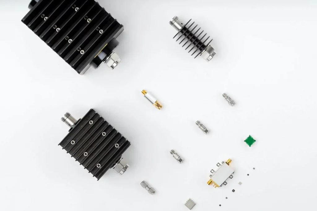
RF attenuators are electronic devices that are used to reduce the amplitude of a radio frequency signal. These devices are used in a wide range of applications, including wireless communication systems, test and measurement equipment, and RF circuit design. RF attenuators can also be used to balance the signal levels in a system, or to protect sensitive equipment from damage caused by high-power signals.
Every Block Covered: Cascaded P1dB and IP3 in a 26 GHz 5G Front-End
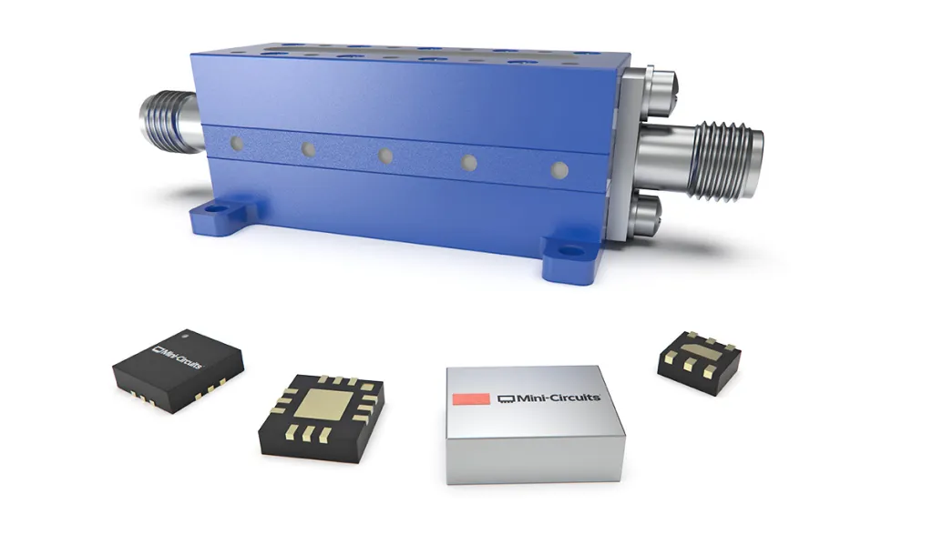
The goal of this article was to provide students and designers alike with a deeper understanding of the equations behind the cascading of P1dB and IP3 as the system expands to include multiple nonlinear components such as those utilized in the RF, frequency conversion and IF sections of a receiver chain. A 5G RF front end was presented for the 24.25 – 25.1 GHz portion of the 5G n258 frequency band comprised of all SMT parts. Calculated data for linearity parameters was presented for individual components in the signal chain as well as cascaded at each stage. The equations used to calculate those results were provided, and an examples were given showing how to calculate cascaded linearity parameters OP1dB and OIP3 from one stage to the next.
Every Block Covered: Noise and Signal-to-Noise Ratio (SNR) in a 26 GHz 5G Front-End

The 24.25 to 27.5 GHz frequency range is also known as the “wider 26 GHz band” or 5G band n258. The Australian Communications and Media Authority (ACMA) “recognized that the wider 26 GHz millimeter wave (mmWave) band was at the forefront of the delivery of mmWave 5G wireless broadband services globally.”2 Consequently, in April 2021, a major portion of that spectrum was auctioned off to operators, predominantly in the 25.1 to 27.5 GHz frequency range.2 The 24.25 to 24.7 GHz band was identified for indoor use and the 24.7 to 25.1 GHz band for indoor/outdoor use.2 For the purposes of the RF front end in this application note, our focus will be on this lower, 24.25 to 25.1 GHz portion of the Australian 5G frequency range.
Linearity – Cascaded P1dB and IP3 for a Simple Microwave Front-End
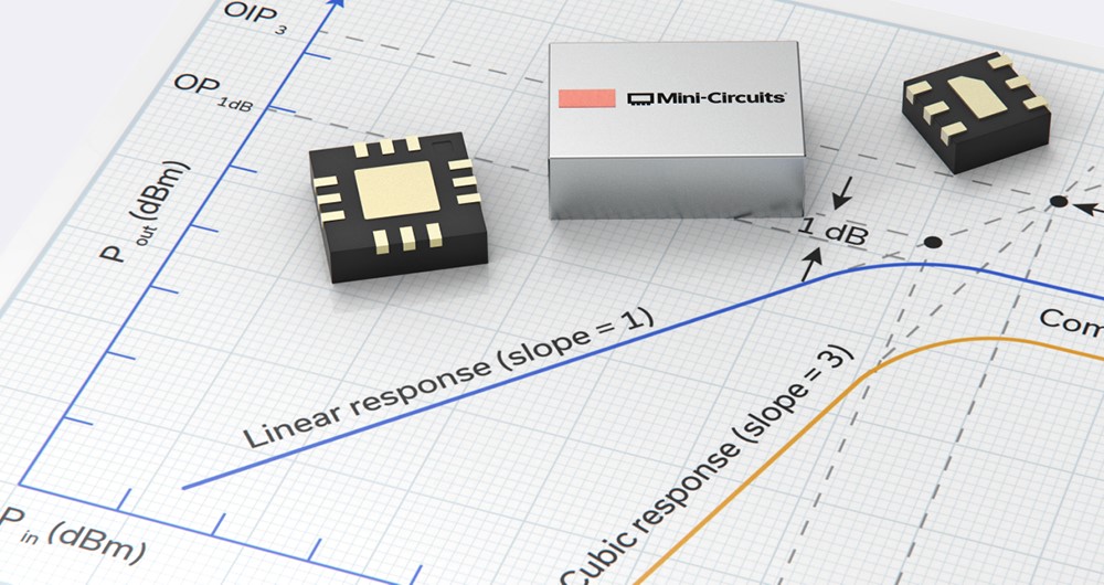
When examining a device data sheet, linearity parameters P1dB and IP3 are straightforward and relatively easy to apply during the design process. Once several components are connected in series in a design, complex equations governing cascaded P1dB and IP3 must be utilized to determine the overall linearity performance of the system or subsystem. The equations utilized to compute P1dB and IP3 provide a means of achieving accurate results in the absence of expensive simulation software. Even though the effect of VSWR interactions between stages is not included when performing the calculations, the results are a good first order approximation of the cascaded performance of the system. The purpose of this application note is to review P1dB and IP3 in general, and to compute these parameters for a basic, three-component RF front end. Other application notes in this series will delve further into the cascading of P1dB and IP3 as the system includes additional nonlinear components such as those utilized in frequency conversion and the accompanying IF components.
MMIC Technologies: Integrated Passive Devices (IPD)
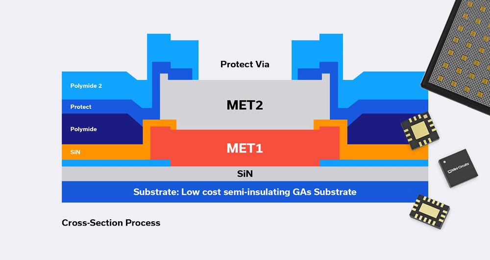
Monolithic Microwave Integrated Circuits (MMICs) with no active elements such as transistors, and containing only passive elements such as resistors, capacitors, inductors, are referred to as Integrated Passive Devices (IPD). These devices do not need DC power to operate, and do not perform frequency conversion as in the case of frequency mixers or frequency multipliers.
What’s the big deal about IPDs? The short answer is they perform vital functions which active elements cannot such as filtering, equalization, balanced-to-unbalanced line conversion (or vice versa) and many more as we will describe later.
Every Block Covered: Noise and Signal-to-Noise Ratio (SNR) in a Simple Microwave Front-End
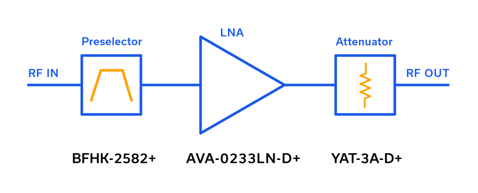
When a technical discussion turns to noise, especially with several cascaded components involved, the calculations and terminology should be straightforward, but often they become more cumbersome than necessary. Signal-to-noise ratio (SNR) is another parameter that should be routinely calculated by the designer but that still creates uncertainty. The purpose of this short applications note is to square-up noise, noise floor, bandwidth and signal-to-noise ratio (SNR) in general, and to compute these parameters for a basic, three-component RF front end. Other application notes in this series dive deeper into the cascading of noise figure (NF), P1dB and IP3.
A Primer on RF Semiconductors (MMICs)
A Primer on RF Semiconductors (MMICs) Radhakrishna Setty, Technical Advisor Introduction Semiconductors are ubiquitous in modern society. In addition to microprocessors for computing technologies, they are used in practically every active wireless communications system including cell phone towers, cell phones, radars and satellites to name a few. Mini-Circuits designs and produces several semiconductor-based (MMIC) components […]
Extending the Performance and Frequency Envelope for QFN Packaging Technology

High-performance, millimeter-wave (mmW) Monolithic Microwave Integrated Circuit (MMIC) products and cost-effective surface mount lead-frame-based packaging typically don’t come up in the same conversation, and for good reason. Just two to three years ago, it was difficult to conceive of operating at frequencies above 20 GHz without considering an expensive, open cavity, High Temperature Co-fired Ceramic (HTCC) package or resorting to more bespoke chip and wire assemblies.
MMIC Die Testing Made Easy with Ultra-Wideband 0 dB Attenuator (Thru-Line) Dice
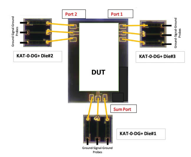
Microwave hybrid circuitry is generally built by integrating several discrete dice via wire bonding. Circuit designers are faced with the task of predicting the performance of hybrids, which comes with some specific challenges.


