Frequency Modulation Fundamentals
Originally a Solution for Eliminating Static
In the 1920s, many brilliant scientists applied themselves to the study of frequency modulation (FM). One of these scientists was a communications systems theorist who worked for AT&T named John Renshaw Carson. Carson performed a comprehensive analysis of FM in his 1922 paper which yielded the Carson bandwidth rule.1 Carson was so convinced that FM was not a suitable solution to the static found in AM transmission systems that he once remarked, “Static, like the poor, will always be with us.”2
Beginning in 1923, in Columbia University’s Marcellus Hartley Research Laboratory, in the basement of Philosophy Hall, a driven genius in electronic circuitry named Edwin Howard Armstrong set out to reduce static through the use of FM. After approximately 8 years of toil, Armstrong had a brainstorm and decided to challenge the assumption that the FM transmission bandwidth had to be narrow to keep noise low. After painstakingly designing this new FM system, with as many as 100 tubes spread over several tables in the laboratory, “[Armstrong] was able to prove that wideband FM made possible a drastic reduction of noise and static.”3 Armstrong was issued patent number US1941069A, which specifically addresses noise suppression in wideband FM, on December 26, 1933, along with three additional patents for FM that same day.
Although FM was fundamentally a far superior broadcasting system to AM, for nearly a quarter century FM struggled to gain the necessary regulatory approvals to achieve full-scale development. Throughout the late 1950s, however, FM steadily increased in popularity. The introduction of high-fidelity FM stereo broadcasting in 1961, something Armstrong laid the groundwork for in his 1953 patent on FM multiplexing, really ensured that FM would make an indelible mark in the radio broadcast industry. Investment in FM infrastructure increased so much throughout the 1960s and 70s, that by the end of the 1970s more listeners tuned into FM stations than AM.4 In addition to broadcasting, FM is utilized in radar (including radar altimeters), seismology, telemetry, wireless microphones, wireless electroencephalograms (EEGs), analog TV audio, analog two-way radios, magnetic tape storage, and cordless telephones.
In this application note, we examine the fundamental mathematics behind FM in the time domain, describe how Armstrong was able to reduce static so dramatically, and describe the basic function of the FMCW radar altimeter.
FM Fundamentals
The easiest way to sense the difference between AM and FM is to listen to the quality of each of their respective broadcasts. AM broadcast stations are limited to 10 kHz of BW, which carries an audio spectrum of up to 5 kHz. More importantly, noise and static electricity are predominantly amplitude-based phenomena and create interference with AM-transmitted signals. Consequently, when AM RF carriers are subjected to high levels of static and noise, their demodulated waveforms yield relatively poor-quality, noisy audio.
FM, on the other hand, is impervious to the vast majority of ambient AM noise and static electrical sources in the atmosphere, even those that are man-made. The dramatic static and interference reduction that is inherent to FM has been evident since Armstrong first transmitted wideband FM for distances of 80 miles from the Empire State Building in 1934 and 1935.5 What, exactly is the mechanism that Armstrong discovered with wideband FM that makes its reception so crystal clear? To answer this question, we turn to the fundamental FM equation shown below:
H(t) = Ac cos[2πfct + mf sin (2πfmt)] [1]
where:
Ac is the carrier amplitude and fc is the carrier frequency
fm is the modulation frequency (or the rate at which the carrier frequency fc is varied up and down)
Δf is the peak frequency deviation (i.e. the carrier frequency fc is varied by a total of ± Δf from nominal)
mf is the modulation index defined as mf = Δf/fm
β is referred to as the deviation ratio, which is the modulation index corresponding to the maximum deviation and maximum modulating frequency β = Δfmax/fm(max)
Whereas mf varies according to the instantaneous values of Δf and fm, β is determined by the maximum values of Δf and fm, and is therefore constant.
Carson’s Rule for estimating the maximum bandwidth occupied by an FM signal is: FM BW = 2(Δf + fm)
Even in the early 1930s, Engineers researching FM, including Armstrong himself were working with what they called “swings” (i.e. 2Δf) of only 25 or 30 “kilocycles” (kHz).6 Since the modulation frequency is equivalent to the audio bandwidth (15 kHz), the FM BW was then approximately:
FM BW = 2(Δf + fm) = 2Δf + 2fm = 30 kHz + 2(15 kHz) = 60 kHz, and β = Δfmax/fm(max) = 15 kHz/15 kHz = 1
Sometime around September of 1931, Armstrong rebuilt his entire setup and “employed a swing of 150 kilocycles [kHz].”7 He therefore used an occupied BW of:
FM BW = 2(Δf + fm) = 2Δf + 2fm = 150 kHz + 2(15 kHz) = 180 kHz and β = Δfmax/fm(max) = 75 kHz/15 kHz = 5.
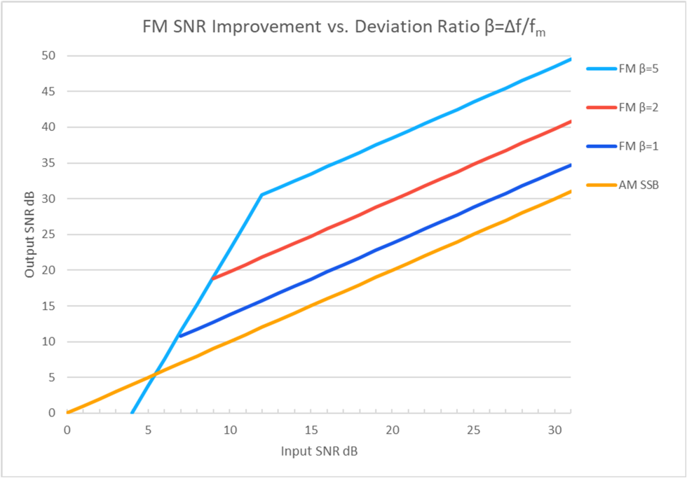
The results were astonishing, as static was suppressed to nearly inaudible levels, and the audio bandwidth tripled to 15 kHz.7 The reason Armstrong’s results were so spectacular can be seen in the graph of input vs. output SNR for FM, plotted for several values of β and shown in Figure 1.8 Provided the input SNR is greater than the threshold (steep portion of the light blue trace) of approximately 10-12 dB for higher values of β, the output SNR is actually improved by the demodulation process. In Armstrong’s case where β = 5, Figure 1 shows an improvement of nearly 20 dB! The β = 1 curve of Figure 1 shows precisely why the researchers’ hesitancy to widen the FM bandwidth (and increase β) led most all of them to conclude that FM offered little, if any advantage over AM; because for the β = 1 curve, the output SNR of FM is very close to that of SSB AM.
FM in the Time Domain
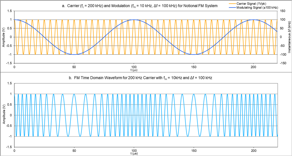
To visualize FM in the time domain, it is most convenient to utilize carrier and modulation signals that are integer multiples of one another. Figure 1 (a) shows a 200 kHz sinusoidal carrier waveform superimposed with a 10 kHz modulating signal. There are exactly 20 carrier cycles per modulating signal period. Figure 1 (b) shows the carrier with modulation applied. Note that as the modulation signal approaches its maximum, the modulated carrier reaches 300 kHz (200 kHz + Δf) and as it approaches its minimum, the instantaneous carrier frequency is 100 kHz (200 kHz – Δf). Although this low carrier frequency is unrealistic, and modern-day FM radio stations span 87.9-108.1 MHz, it serves to help illustrate the expansion and compression of the period as the carrier is frequency-modulated over time.
Frequency-Modulated Continuous Wave (FMCW) Radar Altimeter
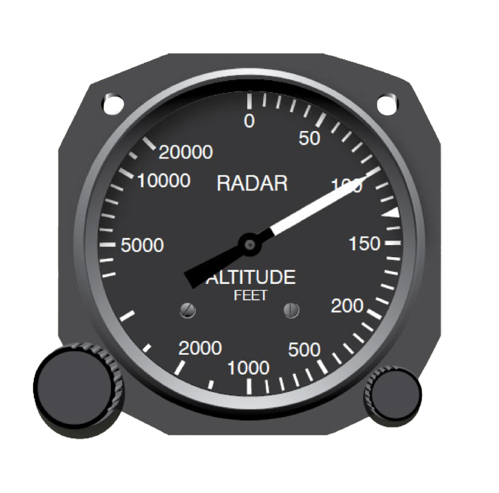
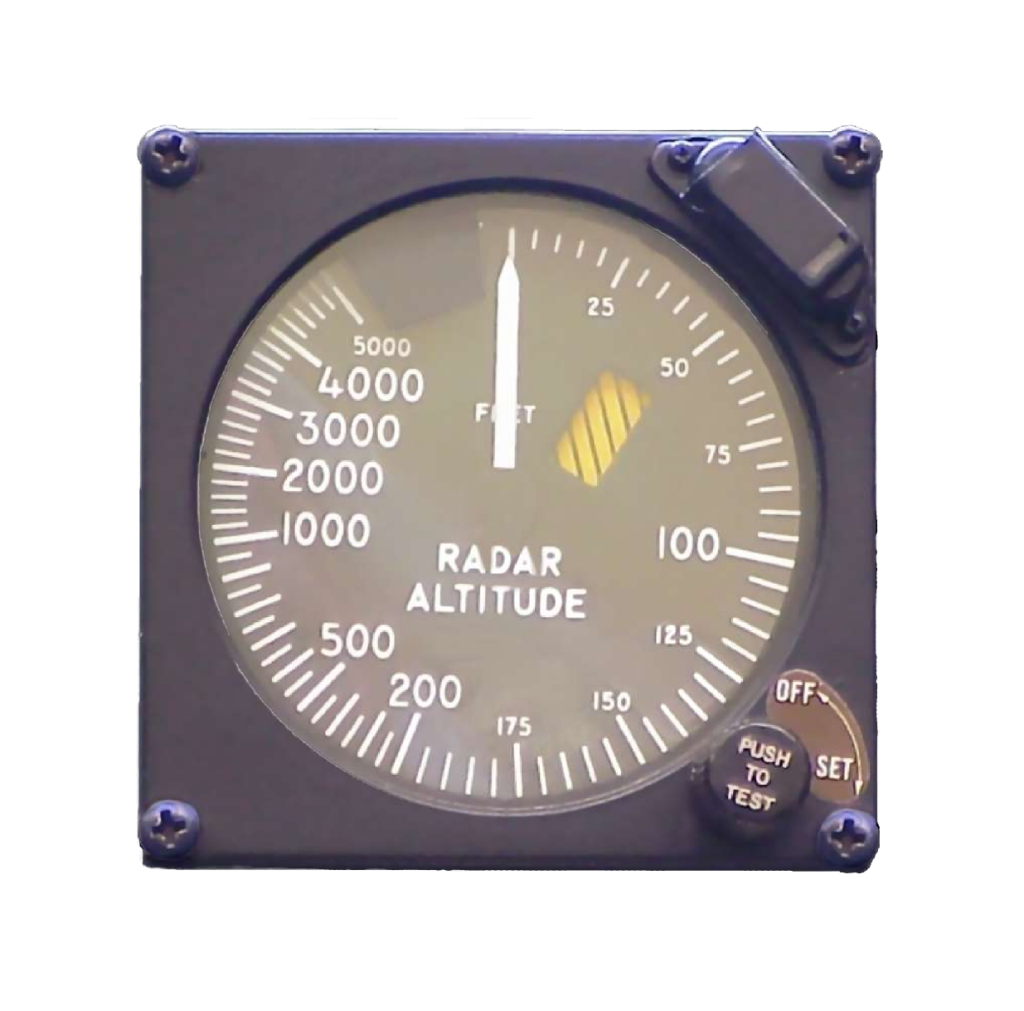
One of the most prolific applications of FM modulation is the FMCW radar altimeter, also called a radio altimeter. For more than 50 years, its basic principle of operation has remained intact, with little to no significant change.9 The reason for the longstanding prevalence of the FMCW radar altimeter over the last half century is because of how effectively and accurately it measures altitude (range), for which we assume the Tx and Rx antennas are pointed from an aircraft toward the ground. For four decades, radar altimeters in civil aviation have used the 4.2-4.4 GHz Aeronautical Radionavigation Service (ARNS) frequency band. Automatic flight control systems and approach/landing systems depend upon the FMCW radar altimeter as its input sensor. It is possible to implement an FMCW radar altimeter using RF/analog circuits in conjunction with a simple method for frequency counting. But just as recent advances in radar technology have led to data digitization at high clock rates while applying digital signal processing, FMCW radar altimeters have utilized these same techniques to achieve high measurement rates and accuracy.
In essence, an FMCW radar altimeter emits a CW transmission on one antenna, receives a reflection (most often called an “echo”) on a separate antenna, and mixes (combines) the two signals to determine altitude. FMCW radars in general are quite effective in determining the velocity of targets by measuring the Doppler shift (named after Physicist Christian Doppler who first described this effect in 1842)10 of the reflected wavefront. We might be tempted to consider the earth a target and design a vertical airspeed measurement system around the FMCW radar concept, however, for this application note, we will focus solely on the details of altitude (range) measurement, since most all aircraft are already equipped with a pitot-static vertical airspeed measurement system.
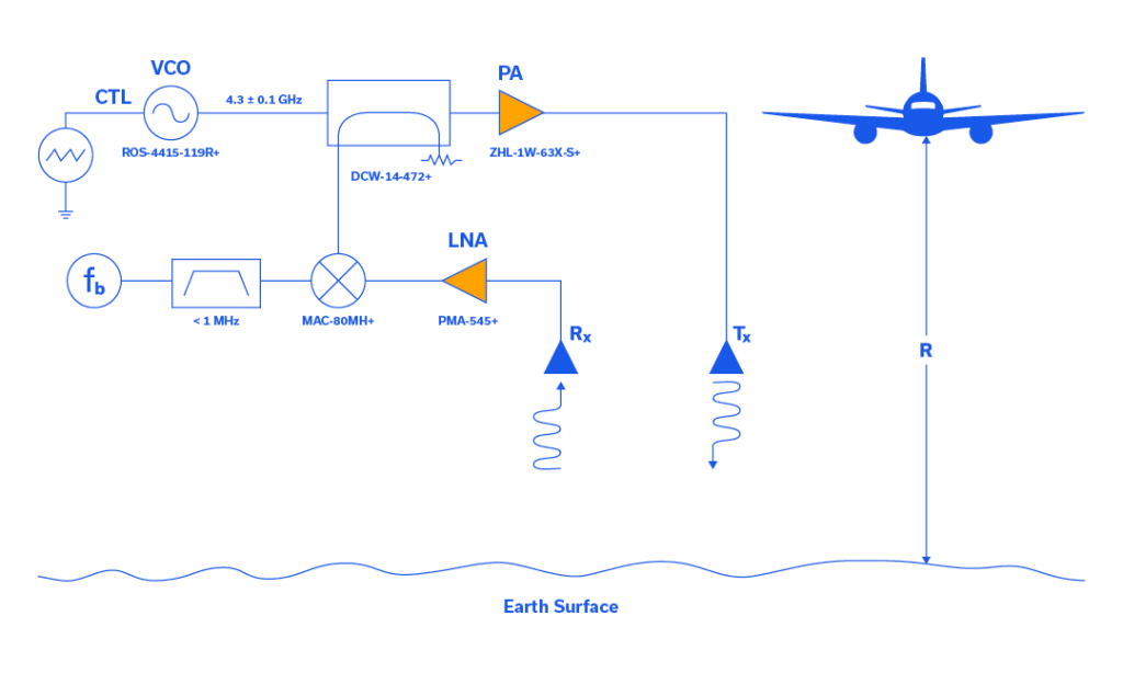
A block diagram for a typical FMCW radar altimeter is shown in Figure 3. Two antennas are directed vertically toward the ground, one for Tx and one for Rx. In the upper lefthand corner of Figure 1, the transmitted wavefront is constructed from a linear, triangular modulation waveform controlling a voltage-controlled oscillator (VCO), the Mini-Circuits’ ROS-4415-119R+. The VCO then outputs the carrier frequency, fc swept linearly higher and lower in frequency by the triangular waveform, generally by approximately ± 50 MHz.
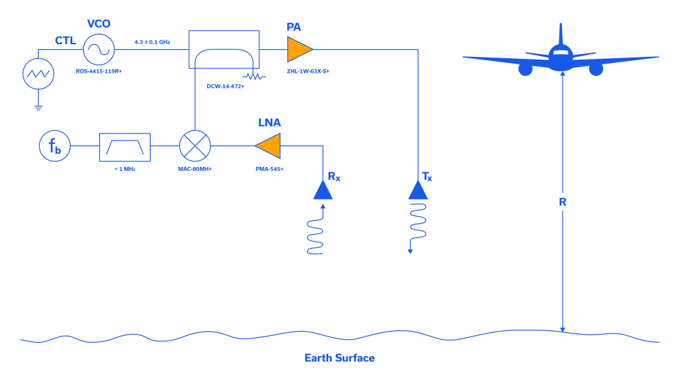
A look-ahead to Figures 4a and 4b shows the modulating signal, the carrier waveform, and the linear-modulated carrier for the transmitter. In Figure 3, the modulated carrier is sampled by a directional coupler, Mini-Circuits’ part number DCW-14-472+, input to the MAC-80MH+ mixer in the receiver, and amplified for transmission to, and reflection from the earth’s surface by the Mini-Circuits’ ZHL-1W-63X-S+ power amplifier (PA). The reflected waveform (the echo) is incident upon the receiver (Rx), passes through the PMA-545+ LNA where it is then mixed with the sample of the Tx waveform. The output of the mixer passes through a low-frequency bandpass filter (< 1 MHz) to eliminate carrier frequency and other noise. The final element in the Rx chain is a method of counting the beat frequency, fb. It is the beat frequency that determines the range, R (also altitude, height) to the target, which in this case is simply the earth’s surface, as shown beneath the aircraft illustration in Figure 3. On a separate note, strict radiated susceptibility limits were never established for legacy FMCW radar altimeters, and there has been concern that adjacent 5G emissions may interfere with FMCW radar altimeter operation. Mini-Circuits published a white paper in Microwave Journal focused on this very subject that offers solutions to this problem, and we welcome you to review it.11
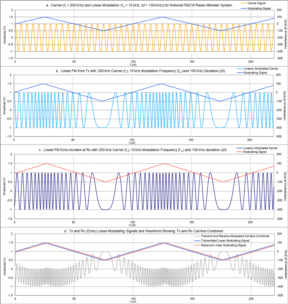
The amazing thing about FMCW operation is that the mixing of the Tx and [delayed] Rx waveforms produces a beat frequency, and it is this beat frequency that determines the altitude, or range. The illustration of this effect is shown in Figure 4b through 4d, where the sinusoidal waveform in 4b is the Tx signal, the waveform in 4c the Rx (echo) signal, and 4d the beat frequency when the two sinusoids are mixed in the receiver. Note that the carrier frequency (fc = 200 kHz) and frequency deviation (Δf = 100 kHz), while unrealistic, have been established to best illustrate FMCW waveforms in the time domain. Also, there is no bandpass filtering applied to the mixed [beat frequency] signal, instead, this signal is a purely mathematical construct wherein the transmitted signal is simply multiplied by the received signal. From the two sinusoidal waveforms in Figures 4b and 4c, or from the modulating signals shown superimposed in Figure 4d, it is apparent that the Rx signal is delayed by approximately 2.5 μs from the Tx signal. While this time delay alone is enough to determine altitude, that task is generally left to pulse-type radar altimeters, and not FMCW. Nevertheless, we’ll begin with time delay in describing how the FMCW radar altimeter functions. Referencing the righthand side of Figure 3, range R can be determined from the time delay td and the speed of light c from:
td = 2R/c and therefore R = c (td)/2, and in our case R = (1ft/ns)(2.5μs)/2 = (1 ft/10-9s)(2.5×10-6s)/2 = 2.5×103 ft/2 = 1250 ft.
This is true because the transmitted wavefront must travel twice the distance R at the speed of light (there-and-back). This time delay calculation will serve as good verification for the accuracy of the following mathematical equations, but it’s worth stating again that time delay is not the measurement methodology for the FMCW radar altimeter, beat frequency is. In fact, many years went by until Armstrong solved the problem that the quantity 2/c became too small to be measured at low altitudes, and therefore the aircraft’s height above ground level could not be determined.9 “[Armstrong’s] patent transformed the problem of measuring a very short time delay (td) when measuring small heights into evaluating low values of [beat] frequency [fb].”9
Beat frequency is derived and applied to the task of determining altitude (height, range (R)) as follows:
R = c(td)/2 = c(fb)/[2(df/dt)] [2]13
R = c(fb)/{2[Δf/(Tm/4)]} [3]
R = c(fb)(Tm)/8(Δf)(fm) [4]
R = c(fb)/8(Δf)(fm) [5]9
R = (1 ft/10-9 s)(10 kHz)/8(100 kHz)(10 kHz)
R = 1 ft/(10-9 s)(8)(105 1/s)
R = 104 ft/8
R = 1250 ft
Where:
c = speed of light (~1 ft/ns)
td = time delay
fb = beat frequency
R = Range (height)
df/dt = frequency change per unit of time
Δf = peak deviation
Tm = modulation period
fm = modulation frequency
While these waveforms and calculations allow the beat frequency and altitude to work out neatly, it is important to point out that an actual radar altimeter utilizes a carrier frequency of 4.3 GHz, as shown in Figure 2. Additionally, the peak deviation Δf is typically 50.106 MHz and the modulating frequency fm only 150 Hz.9 If we recalculate the beat frequency fb for an altitude of 1250 feet using the 4.3 GHz radar altimeter parameters we have:
fb = 8(Δf)(fm)(R)/c
fb = 8(50.106 MHz)(150 Hz)(1250 ft)/(1 ft/ns)
fb = 8(5.0106 x 10⁷(1/s))(1.5 x 102(1/s))(1250 ft)/(1 ft/10–9s)
fb = 8(5.0106 (1/s)(1.5)(1250)
fb = 75.159 kHz
For this combination of radar altimeter parameters, the beat frequency fb is approximately 6 kHz at just 100 feet above ground level and 3 kHz at 50 feet, frequencies that are very easy to measure with high precision. Armstrong utilized FM to measure these low beat frequencies at low altitudes, enabling him to determine altitude with great precision, even for an RF signal whose round trip took only 100 ns at 50 feet in altitude.
FM Applications
In this application note, we examined the history of the development of FM and its main equation in the time domain. We explained why Edwin H. Armstrong was able to reduce static so dramatically using his wideband FM system. The radar altimeter was chosen out of the many important developments in FM to give the reader a sense of how FM can perform the ranging function in an aircraft-to-ground level scenario. Range was derived mathematically from beat frequency and FM modulation parameters and calculated for the notional radar altimeter system. The beat frequency was then determined for real-world radar altimeter parameters for a fixed time delay. Armstrong was given credit for making possible the measurement of very low altitudes, for which time delays are only in the tens to hundreds of nanoseconds.
FM is all around us and is utilized in radar (including EW countermeasures), seismology, telemetry, wireless microphones, wireless electroencephalograms (EEGs), analog TV audio, analog two-way radios, magnetic tape storage, and cordless telephones. While not the most bandwidth-efficient modulation scheme around, FM broadcasting, along with many of the applications mentioned herein is here to stay.
References
- John Renshaw Carson – Wikipedia
- Celebrating 100 Years of Edwin Armstrong’s “Regenerative Circuit” (Sept 22, 1912) — Amplifier
- Edwin Armstrong: Pioneer of the Airwaves | Columbia Magazine IEEE Xplore Full-Text PDF:
- FM broadcasting in the United States – Wikipedia
- Edwin Howard Armstrong – Wikipedia
- Project MUSE – Early FM Radio (jhu.edu)
- Armstrong’s invention of noise-suppressing FM [History of Communications] | IEEE Journals & Magazine | IEEE Xplore
- Modeled after Figure 29.8 of AFM+NoiseL29 (charleslee.yolasite.com)
- The Method of Evaluation of Radio Altimeter Methodological Error in Laboratory Environment – PMC (nih.gov)
- Doppler effect – Wikipedia
- Filtering Solutions for 5G C-Band Interference with Radar Altimeter Receivers | Microwave Journal
- FAA To Take Regulatory Action Over 5G Altimeter Interference – AVweb
- Radartutorial
- DESIGN OF A FAST FMCW RADAR ALTIMETER WITH HIGH ACCURACY, Atmaz, Ersin Tuna M.S., Department of Electrical and Electronics Engineering, THE GRADUATE SCHOOL OF NATURAL AND APPLIED SCIENCES OF MIDDLE EAST TECHNICAL UNIVERSITY, Supervisor: Prof. Dr. Şimşek Demir, September 2023, 90 pages,


