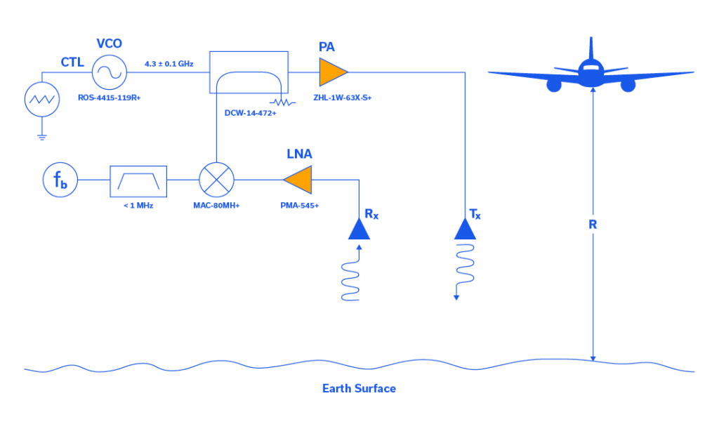
Frequency Modulation Fundamentals

In the 1920s, many brilliant scientists applied themselves to the study of frequency modulation (FM). One of these scientists was a communications systems theorist who worked for AT&T named John Renshaw Carson. Carson performed a comprehensive analysis of FM in his 1922 paper which yielded the Carson bandwidth rule.1 Carson was so convinced that FM was not a suitable solution to the static found in AM transmission systems that he once remarked, “Static, like the poor, will always be with us.”2
Beginning in 1923, in Columbia University’s Marcellus Hartley Research Laboratory, in the basement of Philosophy Hall, a driven genius in electronic circuitry named Edwin Howard Armstrong set out to reduce static through the use of FM. After approximately 8 years of toil, Armstrong had a brainstorm and decided to challenge the assumption that the FM transmission bandwidth had to be narrow to keep noise low. After painstakingly designing this new FM system, with as many as 100 tubes spread over several tables in the laboratory, “[Armstrong] was able to prove that wideband FM made possible a drastic reduction of noise and static.”3 Armstrong was issued patent number US1941069A, which specifically addresses noise suppression in wideband FM, on December 26, 1933, along with three additional patents for FM that same day.
Channelizing High-Power SMT Couplers to Optimize Coupling, Directivity & Isolation

An ideal directional coupler has 0 dB of insertion loss, a constant coupling value vs. frequency, and infinite isolation and directivity. However, the physical, internal construction of directional couplers introduces frequency-dependent losses and finite isolation and directivity. Compounding these internal effects, PCB-mounted couplers face additional challenges. Stray coupling from port to port on a PCB-mounted directional coupler can have significant, adverse effects on the coupler isolation, directivity and even coupling value.
Fortunately, many packaging and shielding methods are available to the designer to mitigate stray coupling. This application note examines form-in-place gasketing for two distinct bidirectional coupler styles: the core & wire and the stripline SMT. Modern day form-in-place gasket machinery is capable of depositing very tiny beads with good adhesion over intricate patterns. The use of conductive silicone elastomers is common, and generally results in high-performance RF/microwave shielding. This technique is
While this application note emphasizes directional coupler external packaging, form-in-place gasket shielding is used broadly to optimize a myriad of components as well as for entire receive and transmit subsystems. This technique is cost effective, repeatable practical to implement in most industry manufacturing environments.
In another application note we will explore some of the more traditional methods of shielding couplers including sheet metal fencing with a lid (commonly referred to as a “doghouse”) and surface-mountable conductive silicone elastomers.
BOOST YOUR KNOWLEDGE: A COMPREHENSIVE GUIDE TO RF COUPLERS – TYPES AND APPLICATIONS EXPLAINED

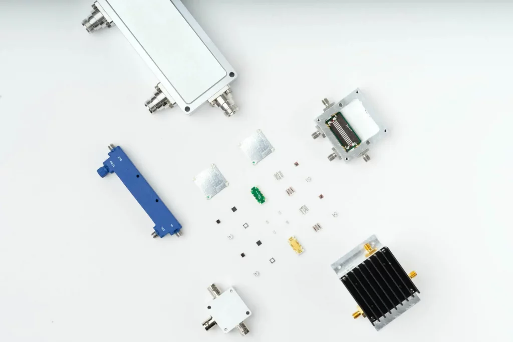
RF Couplers are devices used to distribute, combine, or sample RF signals. They are used in a wide range of applications, including wireless communication systems, test and measurement equipment, and RF circuit design. RF couplers can also be used to monitor or measure the power levels of a signal or to protect sensitive equipment from high-power signals.
There are several different types of RF couplers, each with their own unique characteristics and uses. In this blog post, we will discuss the different types of RF couplers and their applications.
There are several different types of RF Cables, each with their own unique characteristics and uses. In this blog post, we will discuss the different types of RF Cables and their applications.
MMIC Technologies: Integrated Passive Devices (IPD)

Monolithic Microwave Integrated Circuits (MMICs) with no active elements such as transistors, and containing only passive elements such as resistors, capacitors, inductors, are referred to as Integrated Passive Devices (IPD). These devices do not need DC power to operate, and do not perform frequency conversion as in the case of frequency mixers or frequency multipliers.
What’s the big deal about IPDs? The short answer is they perform vital functions which active elements cannot such as filtering, equalization, balanced-to-unbalanced line conversion (or vice versa) and many more as we will describe later.
A Primer on RF Semiconductors (MMICs)
A Primer on RF Semiconductors (MMICs) Radhakrishna Setty, Technical Advisor Introduction Semiconductors are ubiquitous in modern society. In addition to microprocessors for computing technologies, they are used in practically every active wireless communications system including cell phone towers, cell phones, radars and satellites to name a few. Mini-Circuits designs and produces several semiconductor-based (MMIC) components […]
Directional Couplers: Their Operation and Application

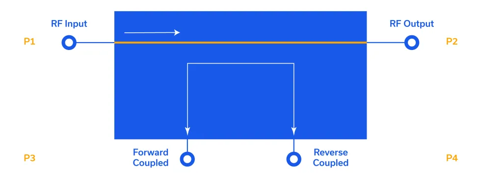
Directional couplers are important devices in RF systems. Their ability to sample either the forward or reverse direction of signal propagation allows a wide range of applications in test, measurement, monitoring, feedback and control. This note should help system designers understand the function, architecture and performance of the coupler, to select a suitable type for their particular application.
Ultra-Wideband, Low-Loss Couplers for Cable TV and Broadband Access Systems (DOCSIS® 3.1)

This article discusses the use of ultra-low loss, broadband distributed couplers in 75Ω systems such as broadband services over cable television networks (CATV).


