Ultra-Wideband, Low-Loss Couplers for Cable TV and Broadband Access Systems (DOCSIS® 3.1)
I. Background
This article discusses the use of ultra-low loss, broadband distributed couplers in 75Ω systems such as broadband services over cable television networks (CATV).
CATV systems require continuous monitoring of output power in the forward (downstream) path throughout the network to ensure consistent signal transmission. This is often achieved by using a low-loss coupler at the output of a power amplifier and adjusting the gain to compensate for any variations in power.
The DOCSIS 3.1 standard specifies a downstream bandwidth from 40 to 1220 MHz. Bandwidth this wide, roughly 30:1, generally necessitates the use of core and wire couplers to achieve the required coupling flatness vs. frequency, and to accurately sample signal power over the full band. While core and wire coupler designs easily cover the required frequency range with excellent flatness, they tend to be lossy, typically sacrificing 1 dB of power or greater. This results in the need for additional power amplifiers or a higher compression amplifier in the transmit path to compensate for those losses, increasing system cost, power dissipation, and component count.
II. Stripline Solution
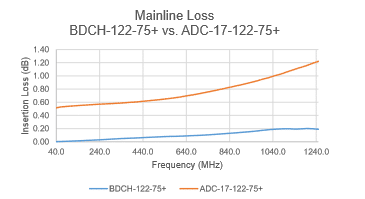
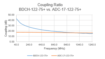
Distributed couplers utilizing stripline construction provide outstanding insertion loss and return loss by comparison to core and wire designs. The trade-off is that they don’t provide flat coupling over the required bandwidth. Figures 1a and 1b below show comparisons of core and wire model ADC-17-122-75+ with a new stripline model BDCH-122-75+. Note that the stripline coupler achieves superior mainline loss, while the core and wire design achieves superior coupling flatness across the band.
While stripline couplers may not provide flat coupling, they do provide excellent repeatability of performance, giving us predictable coupling values at a given frequency. This makes it possible to compensate for frequency-dependent variations in coupling by adding a fixed equalizer on the coupling line. This approach is described in detail below using model BDCH-122-75+.
Mini-Circuits’ BDCH-122-75+ stripline-based coupler has a frequency range from 40 to 1250 MHz with 2W RF input power handling, just 0.15 dB mainline loss and 25 dB typical return loss. While its coupling response varies over frequency, its high-quality stripline construction ensures that those variations are highly repeatable, and the methods discussed below may be used to design BDCH-122-75+ into DOCSIS 3.1 systems and exploit the low insertion loss of the stripline design.
III. Flattening Coupling Attenuation with a Fixed Equalizer
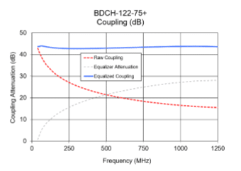
Figure 2 shows a functional schematic of BDCH-12275+ on a transmission line with an equalizer on the coupling line to compensate for the variations in coupling attenuation. The equalizer’s attenuation will increase over frequency as coupling attenuation decreases. When combined in series on the coupling line as shown in the configuration below, the equalizer will produce flat coupling attenuation over the entire 40 to 1250 MHz band.

As proof of concept, Mini-Circuits developed a custom fixed equalizer to pair with BDCH-122-75+. As shown in the measurement plot in figure 3, with a well-designed equalizer, BDCH-122-75+ can achieve coupling flatness of better than ±1 dB over the full DOCSIS 3.1 downstream band. The result is an extremely low-loss coupler for broadband 75Ω systems with 44 dB nominal coupling.
IV. Conclusion
Using conventional coupler approaches, monitoring forward path output power from the head-end and network nodes in DOCSIS 3.1 systems would require a trade-off of thru power in order to achieve the necessary coupling flatness for accurate power sampling and gain control. However, by exploiting the predictable variation in coupling attenuation of Mini-Circuits’ stripline coupler, BDCH-122-75+, customers can use a fixed equalizer to achieve flat coupling over the full downstream band while also benefiting from the low insertion loss and excellent return loss of the stripline coupler design. This approach provides an ideal solution for power monitoring in CATV and broadband access systems conforming to the DOCSIS 3.1 standard.
The technique illustrated in this article may also be used in other applications that require both flat coupling and outstanding signal power transmission across wide bandwidths. Mini-Circuits offers a selection of distributed, stripline coupler models for 50Ω and 75Ω circuits spanning 50 MHz to 6 GHz. For custom fixed equalizer designs for your board, please contact [email protected] or your authorized Mini-Circuits sales representative.
View all RF couplers


