Selecting VCOs for Clock Timing Circuits – A System Perspective

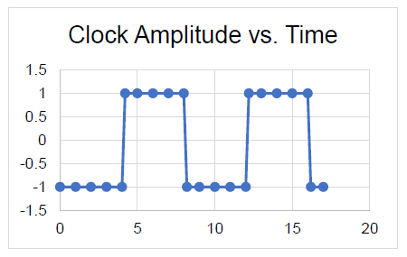
Timing is critical in digital systems, especially in electronic systems that feature high-speed data converters and high-resolution sampling. A clock source is the “timekeeper” and the system performance depends upon the effectiveness of this component. For some system designers, implementing a clock source automatically means using a crystal oscillator, typically a single-frequency source. But other designers, especially those tasked with synchronizing systems at multiple clock frequencies, have learned to appreciate the flexibility of using voltage-controlled oscillators (VCOs) as clock sources.
Frequency Modulation Fundamentals

In the 1920s, many brilliant scientists applied themselves to the study of frequency modulation (FM). One of these scientists was a communications systems theorist who worked for AT&T named John Renshaw Carson. Carson performed a comprehensive analysis of FM in his 1922 paper which yielded the Carson bandwidth rule.1 Carson was so convinced that FM was not a suitable solution to the static found in AM transmission systems that he once remarked, “Static, like the poor, will always be with us.”2
Beginning in 1923, in Columbia University’s Marcellus Hartley Research Laboratory, in the basement of Philosophy Hall, a driven genius in electronic circuitry named Edwin Howard Armstrong set out to reduce static through the use of FM. After approximately 8 years of toil, Armstrong had a brainstorm and decided to challenge the assumption that the FM transmission bandwidth had to be narrow to keep noise low. After painstakingly designing this new FM system, with as many as 100 tubes spread over several tables in the laboratory, “[Armstrong] was able to prove that wideband FM made possible a drastic reduction of noise and static.”3 Armstrong was issued patent number US1941069A, which specifically addresses noise suppression in wideband FM, on December 26, 1933, along with three additional patents for FM that same day.
Specifying VCOs for Clock Timing Circuits | Application Note

Timing is everything for many systems, especially for modern electronic systems with high-speed data converters and high-resolution sampling. A clock source is “the keeper of time” in these systems and system timing performance is very much dependent upon the performance of its clock source. For some system designers, a clock source automatically means a crystal oscillator, typically a single-frequency source. But some system designers, especially those faced with synchronizing systems at multiple clock frequencies, have learned to appreciate the flexibility of using voltage-controlled oscillators (VCOs) as clock sources.
Line Stretchers Ease VCO Load-Pull Testing

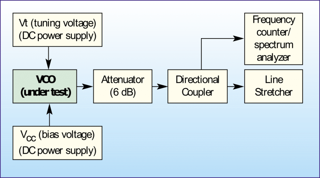
Voltage Controlled Oscillators (VCOs) are normally designed for operation in an ideal 50 ohm environment. However, the actual load that these oscillators must drive are considerably different. It is a standard industry practice to measure frequency variation when the VCO output realizes a load with 12dB return loss (for all possible phase angles). This is usually performed as a manual measurement and is very time consuming. It may take a skilled technician several minutes to several hours. Fortunately, with the development of a novel electronic line stretcher from Mini-Circuits, these once tedious tests can now be executed quickly and a automatically.


