Line Stretchers Ease VCO Load-Pull Testing
Electronic line stretchers offer controlled phase shifts over wide frequency ranges to simplify once tedious VCO measurements.
Aharon Sagiv/Mini-Circuits Applications
Voltage Controlled Oscillators (VCOs) are normally designed for operation in an ideal 50 ohm environment. However, the actual load that these oscillators must drive are considerably different. It is a standard industry practice to measure frequency variation when the VCO output realizes a load with 12dB return loss (for all possible phase angles). This is usually performed as a manual measurement and is very time consuming. It may take a skilled technician several minutes to several hours. Fortunately, with the development of a novel electronic line stretcher from Mini-Circuits, these once tedious tests can now be executed quickly and a automatically.
To understand the significance of the new electronic line stretcher, it may help to review the traditional method of performing load pull tests on a VCO. A manual measurement setup for load pull testing of RF and microwave VCOs is shown in Fig. 1. The VCO’s RF output is connected through a 6dB attenuator and a directional coupler to the low loss mechanical line stretcher. The directional coupler provides a low level (reduced by the coupling factor of the component) signal for frequency monitoring with a frequency counter or spectrum analyzer. The line stretcher must at least be capable of providing a full 360-deg. phase shift over the full frequency tuning range of the VCO.

During testing, the VCO is biased with the Vcc power supply. The VCO’s tuning voltage, Vt, is fixed at a particular voltage in order to fix the frequency of the VCO. At this point, the mechanical line stretcher is manually tuned to cover the full 360-deg. phase shift at that tuned frequency. The maximum and minimum frequencies resulting from the phase shifts are then measured and recorded. The difference in frequencies provides the frequency shift of the VCO as a result of load pulling. Mechanical line stretchers which can provide the full 360-deg. phase shift at frequencies above 1000MHz are available. At lower frequencies however, it is difficult to find continuously variable mechanical line stretchers with adequate load pull testing. Due to this short-coming, lower frequency measurements are created by adding fixed lengths of transmission lines to higher frequency line stretchers to increase the phase shift range at lower frequencies. In addition, using precision open-end and short-calibration standards as termination to the line stretcher, additional 180-deg. phase shift can be obtained. For example, a particular mechanical line stretcher can provide a 360-deg. phase shift at 1000MHz. The same line stretcher will only provide a phase shift of 180-deg. at one half the frequency, or 500MHz. To perform load pull testing on a VCO with a carrier frequency of 500MHz, first a frequency extreme search (for the minimum and maximum frequencies) is performed over the 180-deg. range of the line stretcher at 500MHz, with an open standard placed at the end of the line stretcher. The open standard is then replaced with a short standard, which provides an additional phase jump of 180-deg., and the frequency-extreme search is repeated. The minimum and maximum oscillator frequencies from both measurements are used to compute the load pull results.
VCO load pull measurements using this approach can become tedious at lower frequencies. For measurements on a VCO with a carrier frequency of 250MHz and a 1000MHz line stretcher, testing must be performed in four steps. At each step, the open-short techniques must be performed and additional quarter wave-length (at 250MHz) transmission lines added to affect a phase jump of 90-deg. The technician performing the measurements must also take into consideration the additional insertion loss of the line stretcher, the loss of the directional coupler, the loss of the added transmission lines, and compensate the value of the attenuator.
Conventional electronic phase shifters can be used for VCO load-pull testing, but these are generally narrowband, with a full 360-deg. phase shift generally available only over a narrow range of a typical VCO’s tuning range. In addition, the insertion loss of an electronic phase shift is not constant across the phase-shift range, but tends to enlarge with increasing phase shift. Phase shifters are also subject to distortion as a result of saturation.


Due to shortcomings of conventional electronic phase shifters and mechanical line stretchers, the engineers at Mini-Circuits sought a better method for performing VCO load-pull measurements. This search resulted in development of a line of electronic line stretchers with full 360-deg. phase shifts across wide frequency ranges (see table). The first three models in this line of electronic line stretchers includes units with an octave or more frequency range over a total range of 110 to 1300MHz. These three-port devices feature a nominal return loss of 10 to 12dB, with electronically adjustable phase ranges of better than 360-deg. for the fully specified operating frequency ranges. A monitor port supplies a sample of the output signal of the VCO under test at reduced amplitude for monitoring and testing purposes.
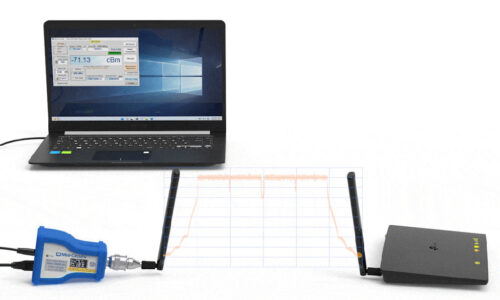
The new electronic line stretchers are ideal for use in automated VCO load-pull test setups (Fig. 2). As the DC control voltage is swept from +0.5 to +25 VDC, the phase angle of the load presented to the VCO changes by more than 360-deg. The VCO/PLL analyzer is set to display the frequency versus DC control voltage (which represents a phase variation of the load). The peak-to-peak difference in the displayed frequency curves provide the load pull (Fig. 3). Each electronic line stretcher is housed in a metal case with female SMA coaxial connectors on all ports.
The metal housing measures 1.25”x1.25”x0.75” (3.18×3.18×1.91 cm).


