A Dual Band Channel Sounder Module for FR1 & FR3 Band Modelling (6.75 GHz & 16.95 GHz)
FR3 Bands: The Goldilocks Zone for Next-Gen 5G & 6G Development?
While much research has been devoted to exploring millimeter-wave bandwidths for high-data-rate wireless communications, much of the deployment of 5G to date has relied on frequencies in the sub-6 GHz (FR1) region of the spectrum. The channel capacity of the FR2 bands has been used in urban environments with high subscriber demand where infrastructure can be installed with sufficient density to compensate for the short range and poor penetration of high-frequency signals. Meanwhile, network operators still rely on lower-frequency signals for more ubiquitous coverage.
Similar desire for the data capacity and speed of millimeter-wave and sub-THz transmissions with broad network coverage and low power requirements of lower frequencies has spurred strong interest in the FR3 bands (7 to 24 GHz) as a possible “Goldilocks zone” for the next phases of 5G and 6G development.
Professor Ted Rappaport and his graduate research fellows of NYU WIRELESS in Brooklyn, New York are among the leading researchers exploring the propagation characteristics of 5G and 6G frequency bands under consideration for commercial use by the ITU and telecom industry. In 2022 Rappaport and his team visited Mini-Circuits’ facilities in Brooklyn, and Deer Park on Long Island as a test bed for their work to develop the first spatial statistical model for ultra-wideband signals above 100 GHz in a real-world factory environment.
Earlier this year, Rappaport returned with a new class of researchers for another project. This time, their aim was to study and compare the penetration loss of FR1(C) (6.75 GHz) and FR3 (16.95 GHz) signals through different materials common in manmade structures that comprise the real-world operating environment. Mini-Circuits facilities offered nothing unique in the way of a test environment that couldn’t be found on campus at NYU, but our Deer Park Technology Center had exactly the capabilities they needed to build the channel sounding hardware they needed for their measurements.
While Mini-Circuits’ Deer Park team is usually dedicated to designing and building the discrete high-frequency components, this was an opportunity to use the portfolio the team has amassed in an integrated system for the benefit of our friends in the research world. What follows will describe the system requirements and present the modules designed and built in-house, almost exclusively using parts from our warehouse right downstairs.
The Project: 6.75 GHz and 16.95 GHz Transmitter/Receiver Modules
The NYU WIRELESS team approached Mini-Circuits VP of Engineering, Joe Merenda and Product Line Engineering Manager for high-frequency products, Dan Ford with a sketch of the block diagram for the system they envisioned. The hardware would consist of Tx and Rx modules for both the FR1(C) (6.75 GHz) and FR3 (16.95) bands of interest. The instrumentation around which their test setup and software was built was limited to frequencies below 8 GHz. This made the system requirement for the FR1 signal straightforward, but the FR3 signal would need to be up and down converted to interface with their equipment.
The IF input on the Tx side and the LO input on both paths were defined by synthesizers NYU had preselected. The rest would need to be designed to meet the desired frequencies, power levels, and spectral purity at each stage of the cascaded system. Merenda and Ford reviewed the concept and searched Mini-Circuits web catalog for components that could be used in a design that would be practical to build and perform within the required parameters. They evaluated the expected system performance and refined their component selection with a homegrown cascade analysis before proposing the solution to Rappaport and his team.
16.95 GHz Block Upconverter Module
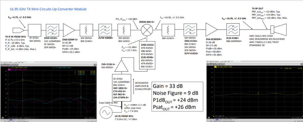
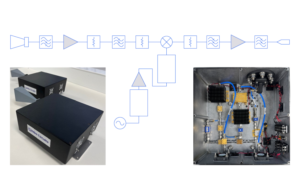
The requirement for the FR3 band Tx module specified an RF output of 16.95 GHz with +24 dBm power at the antenna. The IF input was given at 6.75 GHz and the LO input at 7.9 GHz. The ZMDB-44H-K+ double-balanced mixer was chosen to deliver the desired frequency conversion. The IF pre-amplifier, LO driver and RF PA were chosen to meet the gain budget in each section.
A combination of low pass and high pass filters were used to achieve a band pass filter response and eliminate any unwanted content. Note the use of a reflectionless high pass filter between the mixer output and PA to terminate harmonics and spurious mixing products in a reactive load, minimizing remixing of reflections from the amplifier input port.
A custom active X3 multiplier module was developed specially for the LO chain to generate the +15 dBm power level needed to drive the mixer. This module is comprised entirely of Mini-Circuits MMIC die parts and was assembled on-premises on the Deer Park Technology Center Micro-Assembly Line.

16.95 GHz Low Noise Block Downconverter Module
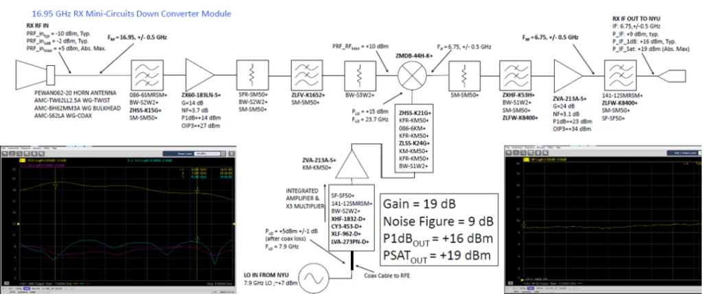
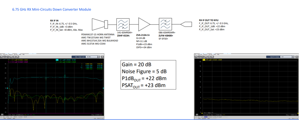
The block diagram for the Rx path was designed to downconvert 16.95 GHz RF signal from the antenna back to the 6.75 GHz IF to interface with the test instrument. Here, the ZX60-183LN-S+ was chosen for the front-end LNA, and the ZVA-213A+ was used as a booster in the IF section. A similar configuration of high pass / low pass filter pairs and attenuators was used to buffer reflections and unwanted mixing products between stages.
6.75 GHz Tx and Rx Modules
Again, because the FR1(C) 6.75 GHz frequency was within the operating range of the research team’s test setup, no frequency conversion was required, rendering the requirements much more straight forward. However, a PA from the RF source to the antenna and a front-end LNA were still needed to extend the output power and increase the receiver dynamic range. In both cases, Mini-Circuits amplifiers were chosen from stock. Filters and pads were added to eliminate any unwanted out-of-band signal.

Research Results
The NYU team went on to use the channel sounder equipment in their work to develop penetration loss models for the bands of interest for ten different building materials common in indoor and outdoor environments. Results for the 6.75 and 16.95 GHz were compared to prior studies of sub-6 GHz, millimeter-wave and Sub-THz frequencies, adding to the body of knowledge on signal propagation used by governments and industry to refine the standards for next-generation wireless networks.
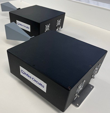
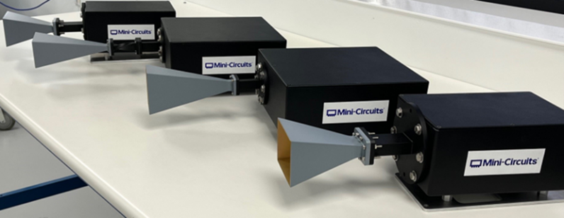
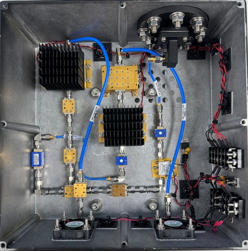
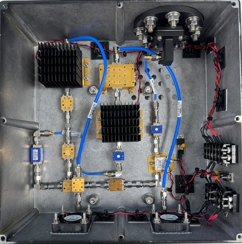
Figure 8: Final channel sounder modules fully assembled.
A paper explaining these findings, titled Wideband Penetration Loss through Building Materials and Partitions at 6.75 GHz in FR1(C) and 16.95 GHz in the FR3 Upper Mid-band Spectrum, will be presented at the 2024 IEEE Global Communications Conference in South Africa. Dipankar Shakya, Mingjun Ying, Theodore S. Rappaport, Hitesh Poddar, Peijie Ma, Yanbo Wang, and Idris Al-Wazani are credited as the authors. Further explanation of how the channel sounder developed by Mini-Circuits was used in their measurements can be found therein.
Future Extensions for High-Frequency Integrated Modules
The success of this collaboration with NYU WIRELESS demonstrated Mini-Circuits’ ability to leverage our extensive portfolio of components with in-house design and advanced assembly capabilities to build integrated solutions for special requirements. The project described above evolved from preliminary concept to delivery of working hardware in about three months. The custom active multiplier module in the LO chain was designed and built in just one week.
While our focus is on design and manufacturing of components used by designers in a wide range of systems, partnering with customers as co-creators at the engineering level has been part of what sets our service to the industry apart throughout our history. Mini-Circuits will consider future opportunities to build integrated high-frequency modules as our business continues to evolve with the needs of the community. Please contact our applications team to explore how the capabilities presented in this article may support your project goals.


