MIMO Systems
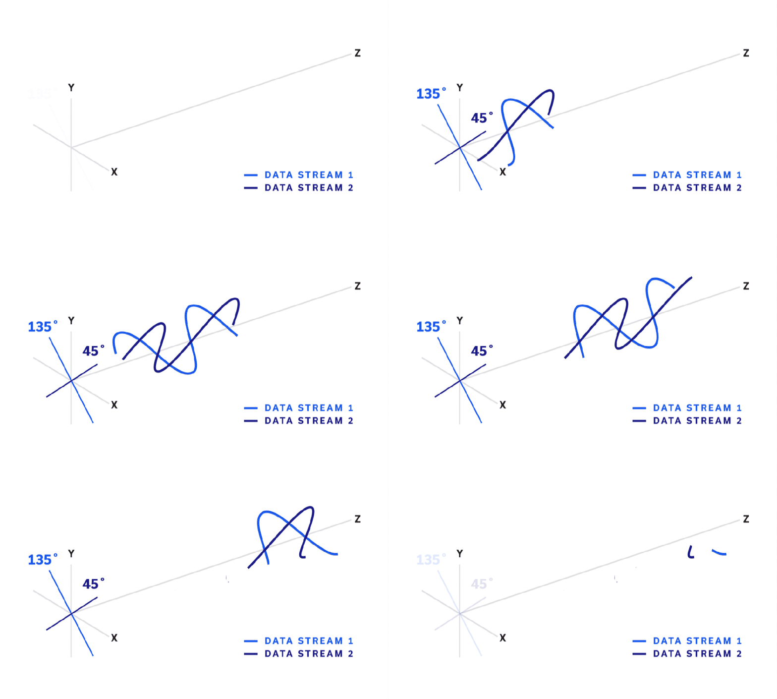
In modern radio communications (particularly commercial cellular and Wi-Fi), Multiple-Input, Multiple-Output (MIMO) is a common method of utilizing multiple transmitting and receiving antennas to increase the capacity of the radio link, reduce errors, and maximize speed. As user demand for bandwidth and data speed have grown, MIMO systems have been integral in the evolution of modern communication systems including cellular communications, Wi-Fi networks and many more.
This article will explore the origins of MIMO technology and explain how concepts of polarization diversity and spatial diversity enable these systems to scale capacity for higher data rates and multiple simultaneous connections to user equipment. Use of MIMO in LTE-Advanced (LTE-A) communications and Wi-Fi 6/6E are then described by way of example.
A Brief Overview of Phased Array Systems
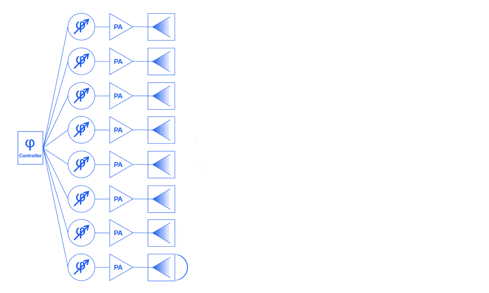
The concept of the phased array antenna system was first put into practice by German Physicist Ferdinand Braun and his assistants in the spring of 1905. In short, he and his assistants carefully controlled the excitation phase of each antenna in an array and determined that the combined effect exhibited significant directivity. In the nearly 12 decades since Braun first described the phased array antenna system, this technology has become commonplace in 4G/5G communications, electronic warfare, radar, nonlethal weaponry, and advanced imaging applications.1
This article begins with an overview of the evolution of phased array systems through history. A functional description of their basic operation in both analog and digital domains is provided, and a brief survey of common and emerging applications is given by way of example.
Channelizing High-Power SMT Couplers to Optimize Coupling, Directivity & Isolation
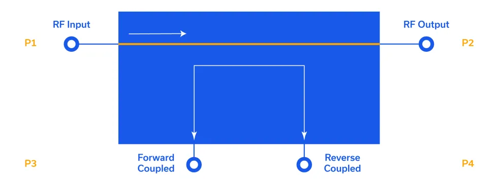
An ideal directional coupler has 0 dB of insertion loss, a constant coupling value vs. frequency, and infinite isolation and directivity. However, the physical, internal construction of directional couplers introduces frequency-dependent losses and finite isolation and directivity. Compounding these internal effects, PCB-mounted couplers face additional challenges. Stray coupling from port to port on a PCB-mounted directional coupler can have significant, adverse effects on the coupler isolation, directivity and even coupling value.
Fortunately, many packaging and shielding methods are available to the designer to mitigate stray coupling. This application note examines form-in-place gasketing for two distinct bidirectional coupler styles: the core & wire and the stripline SMT. Modern day form-in-place gasket machinery is capable of depositing very tiny beads with good adhesion over intricate patterns. The use of conductive silicone elastomers is common, and generally results in high-performance RF/microwave shielding. This technique is
While this application note emphasizes directional coupler external packaging, form-in-place gasket shielding is used broadly to optimize a myriad of components as well as for entire receive and transmit subsystems. This technique is cost effective, repeatable practical to implement in most industry manufacturing environments.
In another application note we will explore some of the more traditional methods of shielding couplers including sheet metal fencing with a lid (commonly referred to as a “doghouse”) and surface-mountable conductive silicone elastomers.
BOOST YOUR KNOWLEDGE: A COMPREHENSIVE GUIDE TO RF FREQUENCY MIXERS – TYPES AND APPLICATIONS EXPLAINED
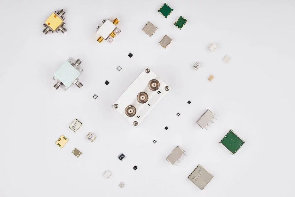
RF frequency mixers are electronic devices that are used to combine two or more RF signals to create a new signal with different frequency characteristics. These devices are used in a wide range of applications, including wireless communication systems, test and measurement equipment, and RF circuit design. RF frequency mixers can also be used to convert a signal from one frequency band to another, or to generate new signals for use in modulation or demodulation.
BOOST YOUR KNOWLEDGE: A COMPREHENSIVE GUIDE TO RF FILTERS – TYPES AND APPLICATIONS EXPLAINED
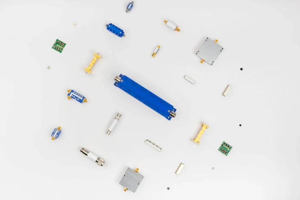
RF filters, also known as radio frequency filters, are electronic devices that are used to selectively pass or block specific frequencies of an RF signal. These devices are used in a wide range of applications, including wireless communication systems, test and measurement equipment, and RF circuit design. RF filters can also be used to remove unwanted interference or noise from a signal, or to separate different signals in a system.
There are several different types of RF filters, each with their own unique characteristics and uses. In this blog post, we will discuss the different types of RF filters and their applications.
A Primer on Quadrature Amplitude Modulation (QAM)
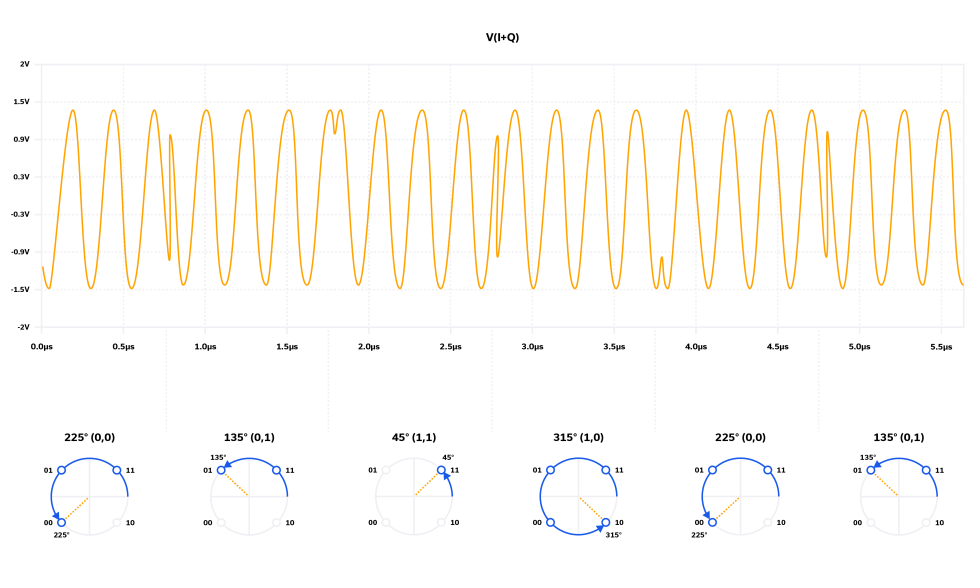
While other modulation schemes discussed in this blog series (pulse, frequency, amplitude, phase) date back to the early chapters of RF engineering history, quadrature amplitude modulation (QAM) was first described by C. R. Cahn in 19602 and evolved steadily over the next few decades. In the last 25 to 30 years, no modulation scheme has seen such widespread development and application as QAM. The technology has played a pivotal role in the industry’s ability to scale data speed and capacity with user demand by packing more data onto the carrier waveform and pushing a fixed channel bandwidth closer to Shannon’s limit. QAM modulation is used widely in cellular networks and backhaul, CATV networks and fixed wireless access points (802.11), and satellite communications to name a few. See Table 3 in Reference [3] for a more detailed list of applications.
In this article, we describe QAM using basic mathematics and illustrate how a QAM modulator operates. We introduce the concept of a constellation diagram and how it relates to the time domain plots for QAM modulation. A representative set of components is then utilized to design a functional QAM modulator by way of illustration. We conclude by describing how the QAM signal is demodulated at the receiver.
BOOST YOUR KNOWLEDGE: A COMPREHENSIVE GUIDE TO RF EQUALIZERS – TYPES AND APPLICATIONS EXPLAINED

RF equalizers, also known as radio frequency equalizers, are electronic devices that are used to adjust the frequency response of an RF signal. These devices are used in a wide range of applications, including wireless communication systems, test and measurement equipment, and RF circuit design. RF equalizers can also be used to improve the performance of a system by compensating for losses or distortion caused by the transmission medium.
There are several different types of RF equalizers, each with their own unique characteristics and uses. In this blog post, we will discuss the different types of RF equalizers and their applications.
BOOST YOUR KNOWLEDGE: A COMPREHENSIVE GUIDE TO RF DC BLOCKS – TYPES AND APPLICATIONS EXPLAINED
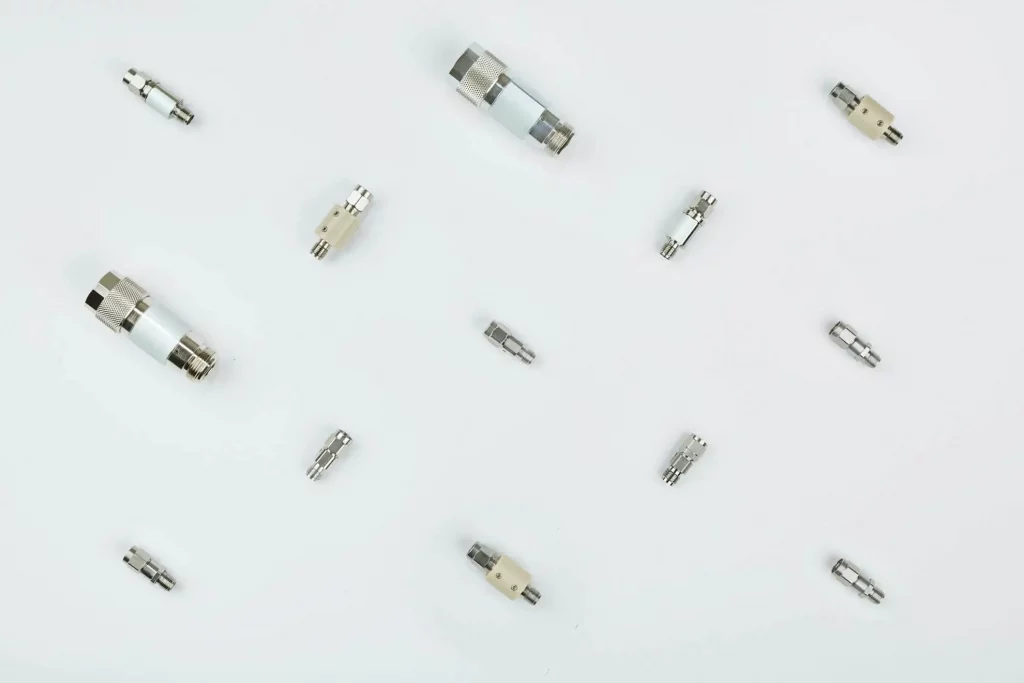
RF DC blocks, also known as radio frequency DC blocks, are electronic devices that are used to prevent DC (direct current) voltage from passing through an RF (radio frequency) signal path. These devices are used in a wide range of applications, including wireless communication systems, test and measurement equipment, and RF circuit design. RF DC blocks can also be used to protect sensitive equipment from damage caused by DC voltage, or to isolate the DC and RF signals in a system.
There are several different types of RF DC blocks, each with their own unique characteristics and uses. In this blog post, we will discuss the different types of RF DC blocks and their applications.
RF/Microwave Bias Tees from Theory to Practice
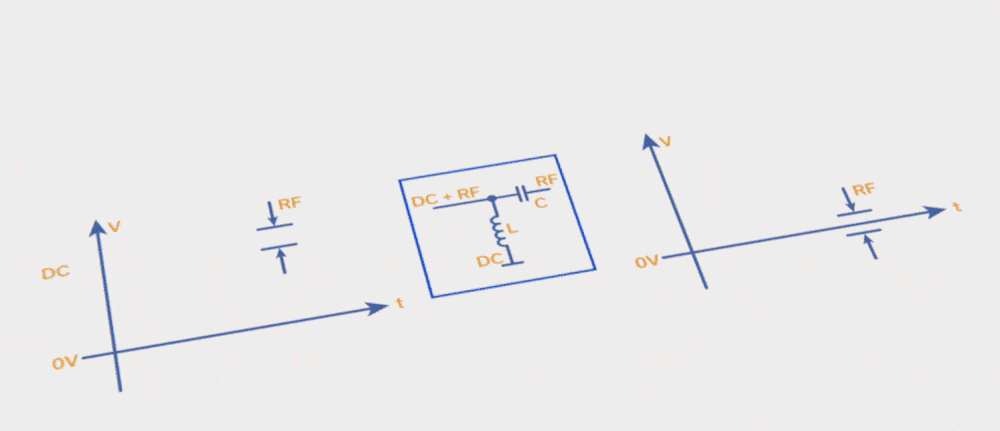
The bias tee is an essential component for applying DC voltage to any component that must also pass RF/microwave signals, most commonly an RF amplifier that requires a DC supply. For narrowband applications, bias tee design and construction are relatively straightforward, provided attention is paid to component self-resonant frequencies (SRFs). For broadband applications, however, bias tee design and construction are nontrivial, and attention to component characteristics is paramount to a successful, high-performance design. In this article, we examine narrowband bias tee design, component SRFs, and how they impact the design, then extend those ideas to broadband bias tees. We will also compare the electrical and physical performance attributes of different types of broadband bias tee designs including discrete circuits with conical inductors as well as MMICs.
Fully Non-Blocking (Full Fan-Out) RF Switch Matrices

The first two articles in this series established that blocking switch matrices use switches to allow one-to-one connections between input and output ports, while non-blocking switch matrices use splitter/combiners on either the input our output ports to allow one-to-many or many-to-one connections. In this article, we’ll examine the fully non-blocking or “full fan-out” configuration in which all inputs are connected simultaneously to all outputs via splitter/combiners, sometimes with programmable attenuation on every path. Features, advantages, applications and examples will be reviewed.


