MIMO Systems
A Brief Primer on Beams and Streams
In modern radio communications (particularly commercial cellular and Wi-Fi), Multiple-Input, Multiple-Output (MIMO) is a common method of utilizing multiple transmitting and receiving antennas to increase the capacity of the radio link, reduce errors, and maximize speed. As user demand for bandwidth and data speed have grown, MIMO systems have been integral in the evolution of modern communication systems including cellular communications, Wi-Fi networks and many more.
This article will explore the origins of MIMO technology and explain how concepts of polarization diversity and spatial diversity enable these systems to scale capacity for higher data rates and multiple simultaneous connections to user equipment. Use of MIMO in LTE-Advanced (LTE-A) communications and Wi-Fi 6/6E are then described by way of example.
The Origins of MIMO
In their research into crosstalk between wire pairs in a cable bundle, A.R. Kaye and D.A. George (1970), Branderburg and Wyner (1974), and W. van Etten (1975, 1976) described some of the mathematical techniques for multi-channel digital transmission that form the basis for MIMO.1 Jack Winters and Jack Salz at Bell Laboratories published several papers on beamforming-related applications in 1984 and 1986.8 In 1993, Arogyaswami Paulraj and Thomas Kailath proposed the concept of spatial multiplexing using MIMO. For this breakthrough they were issued US patent no. 5,345,599 in 1994 for spatial multiplexing with an emphasis on wireless broadcast applications.8 In fact, Arogyaswami Paulraj was awarded the prestigious Marconi Society prize in 2014 for “His idea for using multiple antennas at both the transmitting and receiving stations – which – …has revolutionized high speed wireless delivery of multimedia services for billions of people.’”9
Polarization Diversity in MIMO Systems
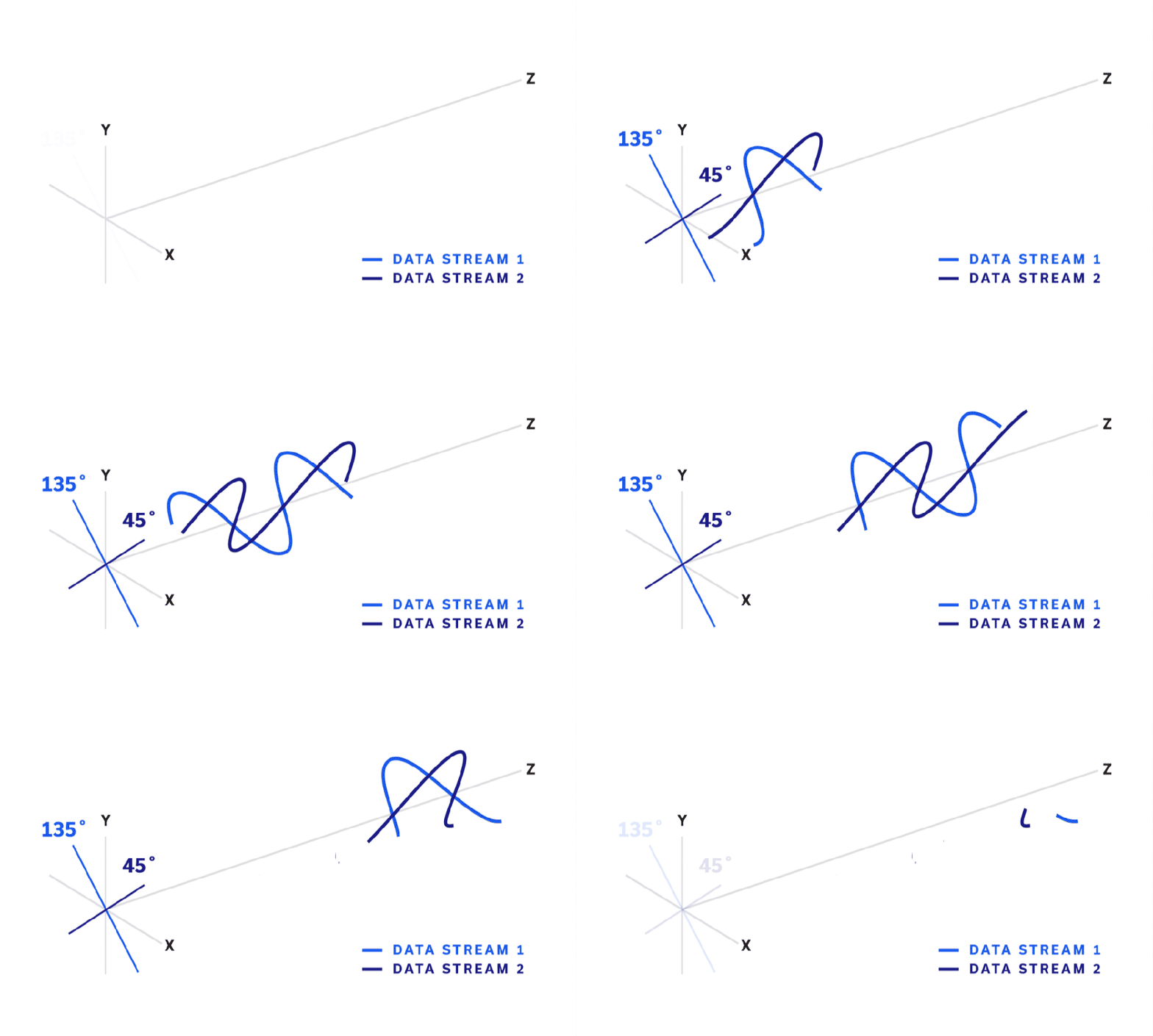
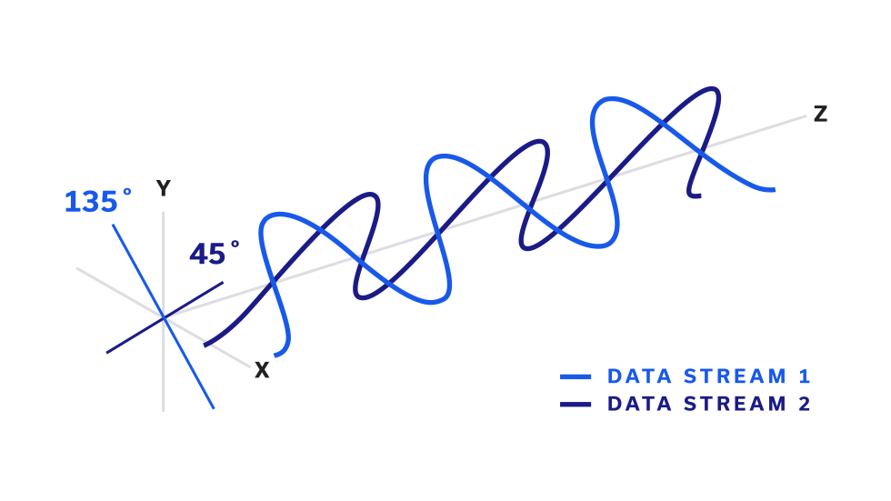
Common MIMO antenna features are polarization and spatial diversity. For polarization diversity, the electric fields of two transmitted signals are oriented 90⁰ apart (e.g. 0/90⁰ (horz/vert), ± 45⁰ (slant)). Figure 1 shows the transmission of slant polarized waves in the direction of the Z-axis. Each of the two waves is itself a data stream, or layer. The entire polarized waveform transmitted down the Z-axis by the ± 45⁰ antenna elements we refer to as a beam.
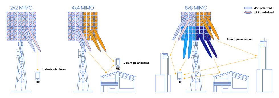
Figure 1 shows a number of beams being transmitted to several instances of UE (User Equipment) on the network. Carefully examine the leftmost cell tower (Base Transceiver Station, or BTS) antenna and UE, the reader will notice what appears like 2 beams is only 1 beam, as stated in the figure. The appearance of two beams and color-coding scheme of one blue bisecting line and one red bisecting line illustrate how two slant polarized data streams comprise a single beam. shown in Figure 1. This basic beam structure, with two orthogonal waveforms is illustrated in Figure 2.
The leftmost BTS in Figure 1 therefore shows polarization diversity equivalent to 2×2 MIMO, which incorporates 2 transmit antennas and 2 receive antennas (2T2R) aligned on the same axis, with slant polarity.
Spatial Diversity in MIMO Systems
Spatial diversity refers to antennas that are physically separated in space. The multiple, often circuitous paths taken by the propagating wavefronts (“multipath” propagation) are utilized to enhance the performance of a MIMO-architected radio frequency system.1 With spatial diversity, multiple data streams can be packed into the same segment of frequency spectrum at the same time and simply transmitted from an ever-so-slightly different location, thereby effecting significant increases in radio channel capacity. As stated previously, multipath reflections serve to enhance the performance of the network instead of compromising it. An example of the multipath phenomenon is shown in the center diagram in Figure 1 where two slant-polarized beams are being transmitted from the BTS to the UE. One is incident directly on the UE via line-of-sight (LOS), while the other is reflected from the roof of a home. In this particular case, the UE must have 4 antennas to receive both data streams on both beams. This is referred to as 4×4 MIMO, or 4T4R. Many modern cellular handsets (smartphones) are built with 4×4 MIMO capability. The Samsung Galaxy® Note 7 and iPhone® XS and XS Max were among the first examples.
Massive MIMO (mMIMO) in LTE Advanced & Beyond
Taking a step up in complexity, the diagram found on the righthand side of Figure 1 shows 4 beams being transmitted: one reaching the UE LOS, one reflecting off a home, and two reflecting of each of two buildings. The transmission and reception of these 4 beams, each containing 2 data streams, constitute an 8×8 MIMO architecture, or 8T8R. Note that while slant polarization is not inextricably linked to every antenna type, it is so common amongst UE as to be considered ubiquitous.
LTE-Advanced (also LTE-+ or LTE-A), first introduced by NTT DoCoMo of Japan and standardized by the 3rd Generation Partnership Project (3GPP) as Release 10 in March 2011, accommodated up to 8 data streams, or 8×8 MIMO.4 For LTE-A, 3GPP releases 12 and 13 introduced the active antenna system (AAS) and massive MIMO (mMIMO) operation.5 An AAS is an antenna system within which active electronics (power amplifiers, low noise amplifiers, variable phase shifters, etc.) are integrated in order to support the transmit and receive functions. Massive MIMO (mMIMO) utilizes real-time beamforming to increase capacity and reduce interference. While definitions of mMIMO vary in practice, for the purposes of this application note we’ll assume that a minimum configuration of 8 transmit/8 receive antennas is required (8×8 MIMO or 8T8R), and that some measure of real-time beamforming is utilized to effect true mMIMO operation.
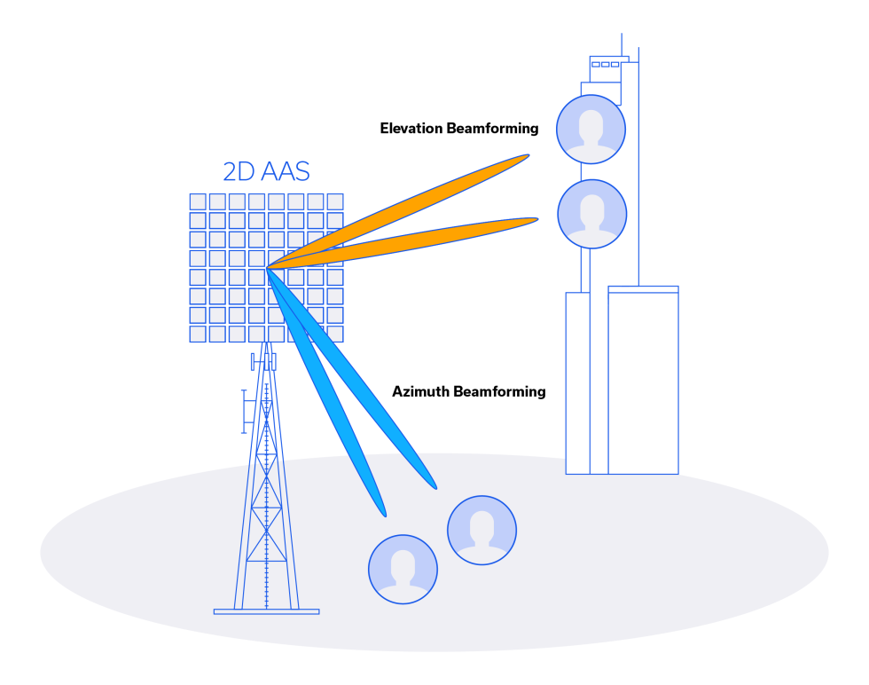
An illustration of how an AAS performs beamforming is shown in Figure 3. The two-dimensional (2D) active antenna system (AAS) transmits 2 beams toward the ground that show a clear variation in azimuth and two directed toward a building that exhibit elevation change. Note that the antenna arrays in Figures 2 and 3 are 8×8 and 4×8, respectively, and capable of supporting more than just a single UE, or cell phone. In fact, modern cell phones support 4×4 MIMO for sub-6 GHz and mmWave 5G. Clearly a preponderance of antenna elements remain capable of supporting quite a number of UE in that particular cell in the network. Cellular networks are certainly a fine example of multiple user MIMO, or MU-MIMO.
MIMO in Wi-Fi 6/6E Systems
The utilization of MIMO in Wi-Fi is considerably simpler in scale than in cellular networks, if only by virtue of the lack of large antenna arrays and the reduced number of users per access point (AP). Nevertheless, MIMO has been a large part of the recent evolution of Wi-Fi and a catalyst for much of the increases seen in downlink and uplink speeds. As shown in Table 1, Wi-Fi 4 was only capable of single-user operation (SU-MIMO) and 2 data streams (2×2 MIMO).
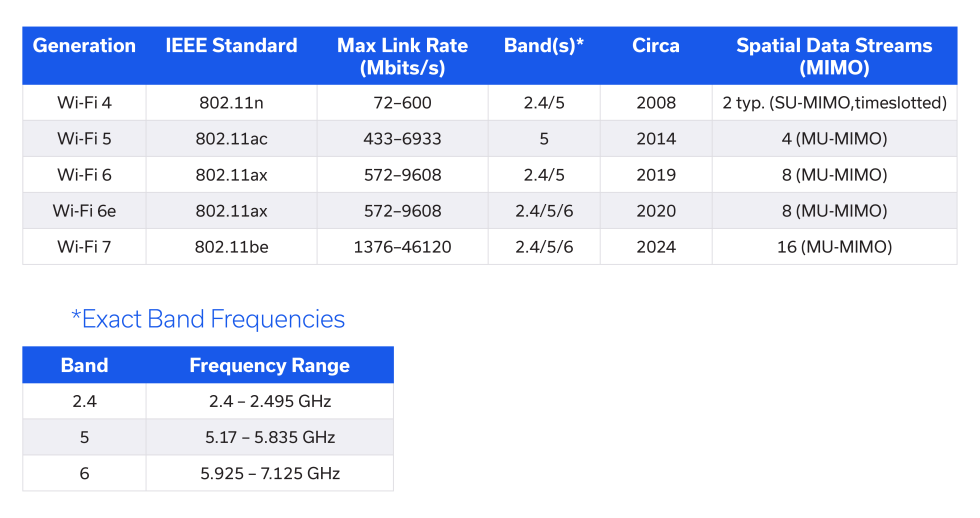
Other users shared the link (or wireless local area network (WLAN)) by being designated timeslots. Wi-Fi 5, or the 802.11ac standard enabled 4 devices to be operated simultaneously through the use of its 4 downlink data streams. A Wi-Fi 6 and/or Wi-Fi 6e AP can downlink to 8 users at a time, and 802.11ax was the first standard in which the capability to perform both downlink and uplink MU-MIMO was incorporated, although not shown in Table 1. Today, most modern cell phones or wireless adapters in PCs and tablets that are Wi-Fi 6/6e capable are 2×2 MIMO, which is still of great benefit in terms of the robustness and speed of the link.
MIMO to Go
This article defined MIMO in general and emphasized polarization diversity as one of the critical features in easily achieving 2 layers of, or 2×2 MIMO. Spatial diversity was discussed in a general context, but with an emphasis on the cellular network. Multiple paths of (multipath) transmission were shown and 2×2 through 8×8 MIMO transmissions from BTSs to UEs were examined in a notional cellular network. Beamforming was introduced, as well as the concept of, and a working definition for massive MIMO (mMIMO). Finally, we surveyed the evolution of Wi-Fi and how MIMO has played a key role in its ever-increasing uplink and downlink speed.
Test Solutions for MIMO Systems
Testing and design validation for MIMO systems is especially challenging due to the need to measure any number of signal paths under different conditions. Mini-Circuits has developed a series of solutions including switch matrices (blocking, non-blocking and full-fanout), programmable attenuators and other functions, allowing operators to automate test signal routing for measurements of complex configurations with multiple signal path combinations and levels. Our flexible platform leverages our wealth of components in-stock to offer standard configurations either off-the-shelf or built-to-order as well as affordable custom designs with fast turnaround.
Explore Mini-Circuits Test Solutions >
References
- MIMO – Wikipedia
- Smart Guides Guide to Understanding MIMO (telcoantennas.com.au)
- 5G NR MIMO 4×4 in DL – 5G NR – telecomHall Forum
- LTE Advanced – Wikipedia
- Electronics | Free Full-Text | A Review on 5G Sub-6 GHz Base Station Antenna Design Challenges (mdpi.com)
- [PDF] Elevation Beamforming With Full Dimension MIMO Architectures in 5G Systems: A Tutorial | Semantic Scholar
- Understanding the Wi-Fi® Variants – Tech Briefs
- History of MIMO | Human Communications Wiki | Fandom
- Arogyaswami Paulraj, 2014 – The Marconi Society


