RF Amplifier and Filter Testing with Mini-Circuits Power Sensors
Introduction
When measuring common RF components, such as filters and amplifiers, RF power sensors provide an accurate, cost-effective way to obtain meaningful data. For RF filters, parameters such as insertion loss, return loss and desired frequency response (passband and stopband) should be considered. For RF amplifiers, gain and one dB compression point (P1dB) can be added to the list of key measurements.
While these parameters are often measured with a variety of high-end test instrumentation such as vector signal generators and network analyzers, the same parameters can be accurately and reliably characterized using scalar measurements, that is measurements of magnitude without phase. Common scalar instruments include spectrum analyzers, power meters and digital volt meters. In this article, we will demonstrate measurement setups for common filter and amplifier parameters using the following Mini-Circuits portable test devices:
- SSG-15G-RC 15 GHz signal generator with USB & Ethernet control
- PWR-18RMS-RC 18 GHz RMS power sensor with USB & Ethernet control
These instruments are capable of making highly accurate scalar measurements. Since vector (phase) capability is unavailable, as with any measurement, care should be taken to minimize systematic and random errors, such as EMI, quality components, proper connector torque and temperature drift. Best practices should always be employed to ensure the highest measurement quality.
Unleveled Gain and Insertion Loss
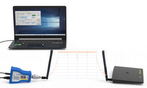
Let’s begin with the most basic layout, using one RF source and one RF sensor. Mini-Circuits ZX75BP-942-S+ (875 to 1010 MHz bandpass filter) will be connected between the RF signal generator and power sensor as shown in Figure 1. With this configuration, it is not possible to capture absolute amplitude measurements, since the accuracy of the RF signal generator is not known. However, the setup is useful as a preliminary measurement.

Assuming the RF signal generator performs reasonably well, a good estimation of insertion loss can be made. However, relative magnitude measurements can be made exactly. For instance, the 3 dB cutoff point from the top of the bandpass response can be accurately performed as illustrated in Figure 2.
In this configuration, the frequency sweep mode of the RF signal generator can be utilized, or the frequency can be tuned manually. The RF power measured by the power sensor is then read directly. As the frequency of the RF signal generator moves, the frequency of the RF power sensor is moved in tandem. Although the power sensor is very broadband, the frequency field applies the calibration factor at the selected frequency to the measurement.
Replacing the filter with an amplifier, the unleveled gain can be measured in a similar fashion. The output power for the RF amplifier is divided by the RF input. Since this is a ratio / relative measurement, the gain will be precise. To measure the one dB compression point at a given frequency, the RF signal generator power can be increased until the RF gain begins to deviate or compress.
The signal generator and power sensors can be controlled using their respective GUIs for a quick and easy test setup, but one of the key features of these test devices is the ability to automate their operation in any modern programming environment. A single Python script or LabVIEW VI (virtual instrument) can quickly be developed to operate the signal generator and power sensor in parallel at each step, setting the signal generator’s CW output, setting the power sensor’s compensation frequency to match, measuring the resultant power, logging the value and proceeding through the rest of the sweep.
Gain / Insertion Loss & Return Loss Measurements
Adding one of Mini-Circuits’ wideband directional couplers and an additional power sensor allows the scalar network analyzer test setup to be expanded to measure return loss in addition to insertion loss. The sensors labelled A (reflected) and B (transmitted) in Figure 2 allow a forward power measurement through the DUT and a reflected measurement from the DUT input to be taken simultaneously. These 2 readings represent the gain / insertion loss, and return loss of the DUT when compared to the known output power from the signal generator.
Since the output power from a signal generator is generally not known to a high level of accuracy, the further addition of a 2-way splitter on the signal generator output (shown in Figure 2) with an additional power sensor R (incident) allows for the measurement of adjusted gain (B/R) and return loss (A/R). Return loss can also be expressed as VSWR, and with the three-USB-sensor configuration in Figure 2, gain and return loss can be measured simultaneously.

With the four separate USB / Ethernet-controlled test instruments (3 power sensors and 1 signal generator) in Figure 2, the case for automating the test setup becomes much more compelling. With a few additional lines of code, all the instruments shown can be integrated into the control program, allowing full automation and parallel measurement from all power sensors. Mini-Circuits’ Applications team is available to provide support and programming examples.
Scalar Analysis Possibilities
Building on the architecture summarized in Figure 2, additional test applications can be developed, including:
- Filters / frequency selective measurements including
band pass flatness, insertion loss, VSWR and return loss - Amplifier measurements:
- Gain
- Gain flatness
- Compression
- VSWR
- Return loss
- Reverse isolation
- Absolute power
- High power
- Mixers / frequency translation measurements including return loss, VSWR, conversion loss, magnitude, compression
- Antenna measurements (far field):
Remote power, transmitted and reflected power
Summary
Mini-Circuits offers a range of power sensors, signal generators and supporting RF components that allow a cost-effective, flexible solution for making accurate, repeatable measurements on RF filters, amplifiers and other RF components. These portable test devices can be arranged in a variety of ways to match the user’s target performance and budget. As with all RF measurements, best practices should be employed to ensure accurate, repeatable measurements are made. This includes sources of systematic and random errors, and is especially true with scalar instruments unable to detect the phase of a signal. Overall, Mini-Circuits test devices and accessory components provide a reliable way to measure the RF performance of a wide range of devices in a variety of settings from design validation to high-volume production test operations.