Fully Non-Blocking (Full Fan-Out) RF Matrices
The first two articles in this series established that blocking switch matrices use switches to allow one-to-one connections between input and output ports, while non-blocking switch matrices use splitter/combiners on either the input our output ports to allow one-to-many or many-to-one connections. In this article, we’ll examine the fully non-blocking or “full fan-out” configuration in which all inputs are connected simultaneously to all outputs via splitter/combiners, sometimes with programmable attenuation on every path. Features, advantages, applications and examples will be reviewed.
Overview
Fully non-blocking matrices (sometimes referred to as full fan-out matrices) are constructed with splitter / combiners on all input and output ports to allow every possible internal path between the group of input ports and the group of output ports. Switches could be used internally to allow each path to be individually connected / disconnected but more commonly, programmable attenuators are used for enhanced functionality. A programmable attenuator with 0-63 dB attenuation range can be considered a type of switch with an “on” state (0 dB) and an “off” state (63 dB), plus the additional benefit of being able to set any path loss within that range. This allows the matrix to go further than just connecting / disconnecting the internal signal paths, with the ability to combine signals at precise levels.
Full Fan-Out Matrix Features:
- Splitter / combiners on input & output ports
- Programmable attenuators for path control
- Many to many configuration
- Bi-directional operation

Switch Path Options
Since every input-to-output port combination is possible, the total number of active paths available within the matrix is equal to the number of inputs multiplied by the number of outputs. The 8 x 8 matrix example of figure 10 permits up to 64 concurrent active paths. All 8 inputs could be simultaneously connected to all 8 outputs in a “many to many” configuration. The use of programmable attenuators as the control element also allows the signal level to be varied independently on each of those 64 paths.
Benefits & Trade-Offs
The benefit of the fully non-blocking matrix is clearly in its complete flexibility of input / output path combinations. This configuration can replace blocking and non-blocking (both fan-out and fan-in) switch matrices, performing all functions simultaneously and open up additional test applications requiring signal level control. The key trade-off is the higher insertion loss since each path would pass through 2 splitter / combiners and a programmable attenuator.
Applications
Full fan-out / fully non-blocking matrices are an ideal configuration for transceiver testing, with a particular focus on cellular handover and eNodeB test systems. By connecting a bank of wireless devices on one side of the matrix with a bank of radio nodes on the other, a wide range of common scenarios can be simulated in the test environment.
For characterization of wireless devices such as cellular handsets, the matrix allows multiple radios and interfering signals to be present at each handset, as they would be in the real world. Adjusting the programmable attenuation on any path, simulates a change in the signal strength between device and radio. Ramping up the attenuation on one path while ramping down the attenuation on the other allows the handover scenario to be tested, where the device switches from one radio to the other as if it was physically moving between base stations.
The same setup can also be used for the opposite use case, testing of the radios / base stations against a bank of cellular handset simulators.
Mini-Circuits’ Solutions
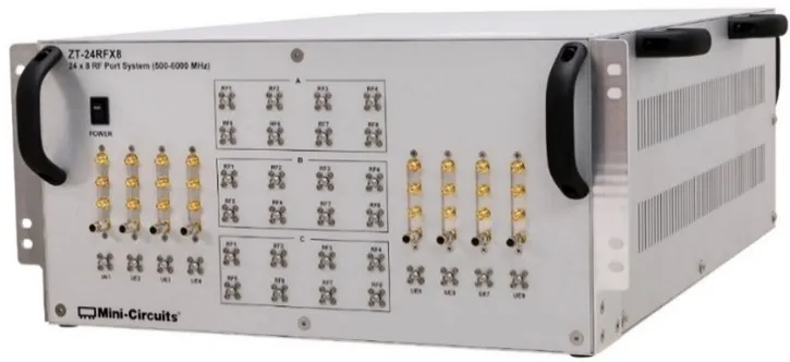
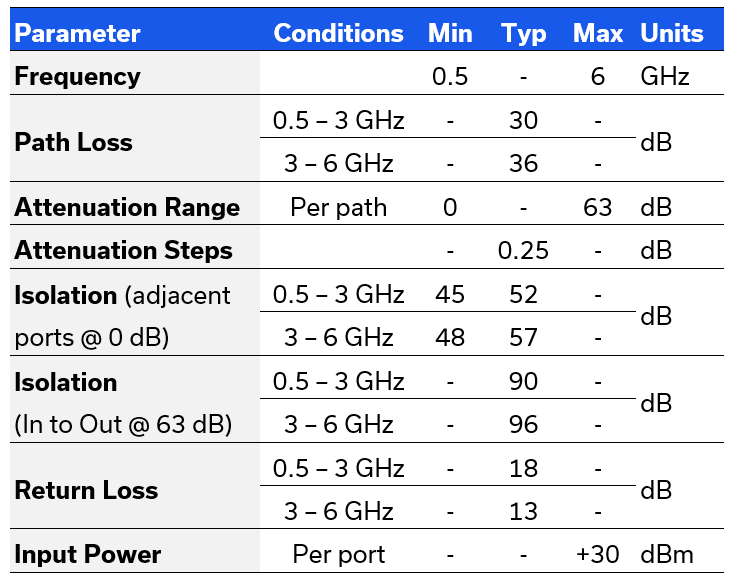
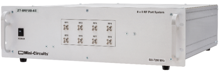
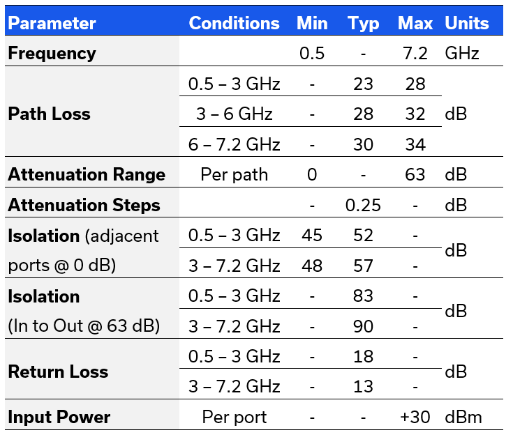
The two models summarized below demonstrate Mini-Circuits’ range of fully non-blocking matrices. ZT-8RFX8 is a compact 8 x 8 matrix covering 0.5 to 7.2 GHz, encompassing most of the common IoT applications, including the 5G FR1, WiFi 6E and ISM bands. ZT-24RFX8 offers a larger port count, with a 24 x 8 configuration and frequency coverage from 0.5 to 6 GHz. Both matrices use a combination of solid-state switches, passive splitter / combiners and programmable attenuators (each with 0-63 dB range) with control via Ethernet or USB and Mini-Circuits’ comprehensive software support
ZT-8RFX8-6E
- 8 x 8 fully non-blocking matrix
- 0-63 dB attenuation per path
- 19” rack-mount chassis, 3U, 20” depth
- SMA female connectors (front & rear)
- Ethernet & USB control
ZT-24RFX8
- 24 x 8 fully non-blocking matrix
- 0-63 dB attenuation per path
- 19” rack-mount chassis, 5U, 30” depth
- SMA female connectors (front & rear)
- Ethernet & USB control
