Mesh Network Simulators for Wireless Device Testing
Lee Whiting, Application Manager, Mini-Circuits Europe
A mesh network is a wireless network architecture in which three or more devices, also called nodes, are all connected to each other. Every node in the mesh network is able to communicate with some or all of the other nodes in the network. This type of architecture is distinct from traditional “hub and spoke” networks in which all devices connect to a central hub through which they communicate with other devices. In the real world, nodes can be wireless routers, cellular handsets, personal computers or any other device capable of sending and receiving signals. Home Wi-Fi networks, local area networking, military and public safety communications are all examples of applications where mesh networks are commonly employed.
For manufacturers of mesh network devices and systems, RF testing needs to account for real-world conditions such as varying distances between devices in the network and loss of connection to one or more nodes. As one can imagine, the more nodes in the mesh, the more complex the test setup becomes. Mini-Circuits has developed a range of mesh network test systems which allow simulation of a “real-world” mesh communication network in the confined space of a development or production environment. Programmable attenuators on each path allow transmission loss to be varied independently between any pair of devices without affecting any other paths.
One of the strengths of a mesh network test system is that the programmable attenuators allow fine control of the transmission loss between the devices, from switching on the path (min. attenuation) to switching off the path (max. attenuation) and everything in between. Being able to set the loss within this range allows a wide range of scenarios to be simulated, such as varying distances between DUTs, moving into and out of range of other DUTs, or blocking and interfering signals of varying levels being introduced.
This article will explain the basics of how Mini-Circuits’ mesh network simulators are built and how they work. Real world applications and system implementations will be explored, and finally, practical instruction will be provided on how to calibrate a mesh network simulator in a typical RF test lab.
Mesh Network Fundamentals
The construction of a mesh network test system relies on passive power splitter/combiners, with all internal ports interconnected via a programmable attenuator. An ideal power splitter would have infinite isolation between its output ports so the programmable attenuator would be the only element dictating the signal power on paths between the external ports. Therefore, each programmable attenuator would represent the transmission loss between a different pair of DUTs (devices under test), simulating cable or wireless transmission losses, for example, with a range of 0-95 dB in 0.25 dB increments.
In practice, the power splitter has leakage across its output ports (defined by its isolation spec), typically on the order of 20 dB for a wideband device. This introduces a number of “unwanted” leakage paths into the mesh for each desired signal path, as indicated in Figure 1.
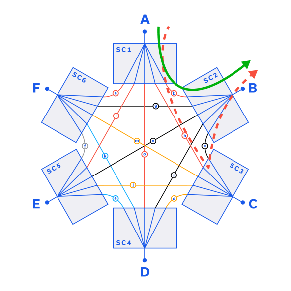
The insertion loss of any wanted signal path between 2 ports (shown by the green arrow in Figure 1) is equal to the loss through 2 splitters, plus the loss through the programmable attenuator (ignoring cable losses for simplicity). The insertion loss of an unwanted leakage path (shown by the red arrow in Figure 1 is equal to the loss through 2 splitters, plus the isolation of a third splitter, plus the loss through 2 programmable attenuators. The isolation of the mesh itself can be considered to be the difference between the insertion loss of a wanted signal path and the insertion loss of an unwanted leakage path.
ILWANTED = ILSPLIT + ILATT + ILSPLIT
= 2ILSPLIT + ILATT
ILLEAKAGE = ILSPLIT + ILATT + ISOSPLIT + ILATT + ILSPLIT
= 2ILSPLIT + 2ILATT + ISOSPLIT
ISOMESH = ILWANTED – ILLEAKAGE
= ILATT + ISOSPLIT
Where:
ILWANTED = Insertion loss of a wanted signal path through the mesh network
ILLEAKAGE = Isolation of an unwanted leakage path through the mesh network
ISOMESH = Isolation of a mesh network path
ILSPLIT = Splitter insertion loss
ILATT = Programmable attenuator insertion loss
ISOSPLIT = Splitter isolation
Mesh Networks: Applications and Use Cases
As we’ve mentioned, mesh networks are employed in a growing number of real-world commercial and military applications. Below are examples of two such applications as well as an illustration of how each is implemented.
Use Case 1: Military VHF/UHF Radios (30-100 MHz)
A common mesh network application involves hand-held / manpack or vehicle-mounted radios issued to military groups or personnel in the field. These radios typically support communication directly between devices, allowing operation in remote locations where no intermediate base-station infrastructure is available to serve as a central “hub.” The mesh concept allows for complete flexibility of communication between the devices.

Use Case 2: Smart Home Devices (700-5900 MHz)
The range of devices available for the “smart home” is growing by the day and includes items such as smart light bulbs, plug sockets, home assistants, thermostats, boiler / radiator controllers and cameras. A common implementation of these devices would see them interconnect in a mesh network using ZigBee, or a similar low power radio standard.
The advantage of the mesh network architecture in this application is that each device is capable of communicating with a number of other devices in range, rather than just to a single common access point, router or base-station. This allows devices to act as network repeaters / extenders, passing communications along the mesh for other devices that might otherwise be out of range of each other. Should any one device fail (for example if the battery was exhausted) there would often be another route available for all other devices to carry on operation. In other words, the network is self-healing.

Example Mesh Test System Implementation
Both of the case studies above could lead to the example scenario represented in Figure 4. The diagram shows six mesh devices under test (DUT) which are connected in 2 groups of 3. The 3 devices within group A are in range of each other, as are the 3 devices in group B. Devices 3 and 4 are also close enough to be able to communicate and relay messages between the groups.
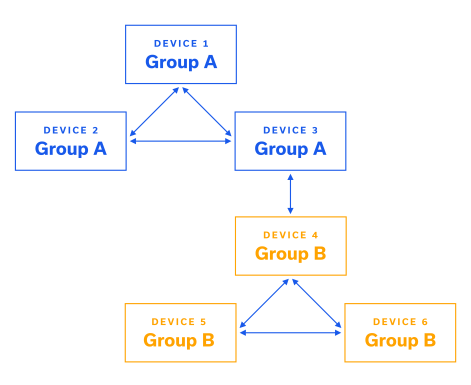
In use case 1 this may represent 2 teams of military personnel or vehicles operating remotely, where 2 radios on the edges of the groups (devices 3 and 4) are also in range of each other and able to relay between the groups. In use case 2 this could represent smart devices spread over two areas of a large building, where only one device in each area is located close enough to the other to be able to bridge the distance.
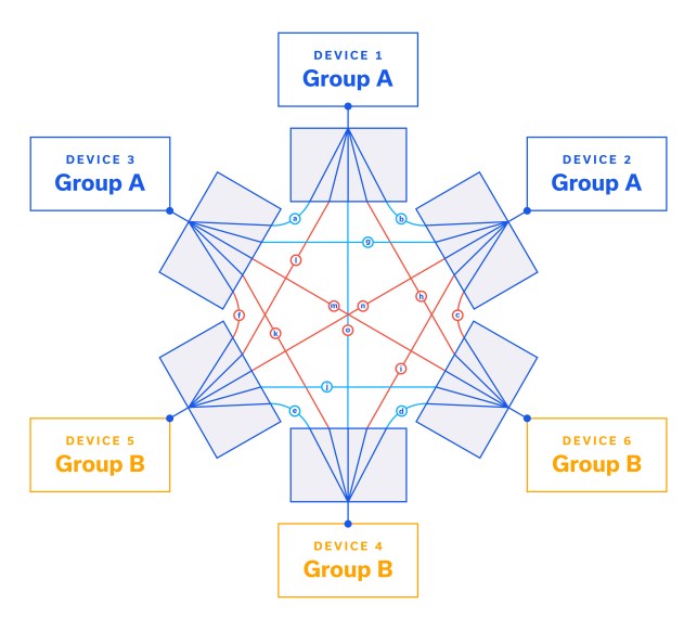
Figure 5 demonstrates how the 6 DUTs in this scenario can be interconnected through a mesh network test system in a production environment. To mimic the allowed interconnections shown in Figure 4, the attenuators on the allowed paths (highlighted green) should be set to low loss. To block the unwanted paths between devices which should not be able to communicate, the attenuators on those paths (highlighted red) should be set to maximum attenuation, this ensures >100 dB isolation between the devices at each end of the paths.
Calibrating a Mesh Network to Eliminate Unwanted Leakage Signals
The importance of the isolation characteristic defined above is that it demonstrates how an increase in attenuation on all paths will increase the loss of all wanted signal paths by that amount while increasing the loss on all unwanted signal paths by twice that amount. This allows the mesh to be “calibrated” by arbitrarily increasing the attenuation on all paths to the point where unwanted signals can no longer be detected (i.e. the signal levels via unwanted paths are reduced until they are in the noise floor or below the input dynamic range of the DUT receivers).
The trade-off is, of course, that setting a new minimum attenuation in this way reduces the usable attenuation range of the mesh, for example if the mesh has 0-95 dB attenuation range but a minimum attenuation of 20 dB is required to reduce the unwanted signal levels to an acceptable level, then the remaining usable attenuation range for each path becomes 20-95 dB.
This process can be demonstrated using the example specifications of Figure 2 for a 6-port mesh network and DUT.
ZTMN-0695B Approximate Specifications
DUT Example Specifications
ILWANTED = 25 dB typ
ILLEAKAGE = 55 dB typ
ISOMESH = 30 dB typ
Tx Power = 20 dBm
Rx Dynamic Range = -70 to 0 dBm
Referring to the block diagram of Fig. 1 and assuming all attenuators are set to 0 dB, the following characteristics would be observed:
An input signal of 20 dBm at port A would reach port B with a level of -5 dBm via the green, wanted path
The same input signal would also reach port B with a level of -35 dBm via the red, unwanted path
In this scenario, the unwanted leakage signals are still within the dynamic range of the DUT at port B so the mesh may not perform its function as expected; setting the attenuation on a wanted signal path between 2 ports may not alter the communication between those ports as the leakage path offers another route.
Since the isolation of a mesh path also includes the programmable attenuation on that path, the minimum attenuation required to drop the unwanted leakage paths below the input range of the DUT can be defined as below.
ATTMIN = (PTX – ILWANTED – ISOMESH – PRX) / 2
Where:
ATTMIN = Minimum programmable attenuator value for full mesh control
PTX = Transmit power level of the DUT
PRX = Minimum receivable power level of the DUT
With the example in the table above, the target could be to reduce the unwanted leakage signal levels to -75 dBm so they are outside the dynamic range of the DUT, with some margin. That requires a minimum attenuation of 20 dB, to reduce the unwanted leakage signal from -55 dBm to -75 dBm:
ATTMIN = (20 – 25 – 30 – (-75)) / 2
= 20 dB
As stated above, the trade-off is that the path loss through the mesh on the wanted paths is also 20 dB higher and so the usable range of the programmable attenuators is also 20 dB less.
Summary
Mini-Circuits offers mesh network simulators in standard configurations from 3 to 9 ports with additional configurations available on request. These systems have been successful in reducing cost, improving test efficiency and speeding up time to market for many customers performing RF testing of mesh network devices and systems. For additional information on Mini-Circuits mesh simulators, visit https://www.mcdi-ltd.com/rf-mesh-network-test-systems/


