A Primer on Quadrature Amplitude Modulation (QAM)
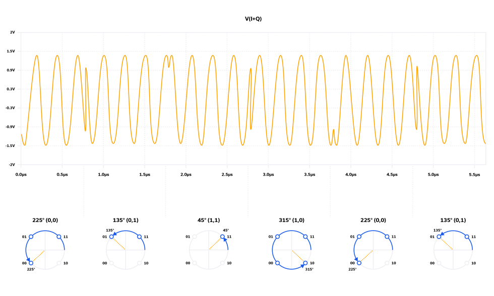
While other modulation schemes discussed in this blog series (pulse, frequency, amplitude, phase) date back to the early chapters of RF engineering history, quadrature amplitude modulation (QAM) was first described by C. R. Cahn in 19602 and evolved steadily over the next few decades. In the last 25 to 30 years, no modulation scheme has seen such widespread development and application as QAM. The technology has played a pivotal role in the industry’s ability to scale data speed and capacity with user demand by packing more data onto the carrier waveform and pushing a fixed channel bandwidth closer to Shannon’s limit. QAM modulation is used widely in cellular networks and backhaul, CATV networks and fixed wireless access points (802.11), and satellite communications to name a few. See Table 3 in Reference [3] for a more detailed list of applications.
In this article, we describe QAM using basic mathematics and illustrate how a QAM modulator operates. We introduce the concept of a constellation diagram and how it relates to the time domain plots for QAM modulation. A representative set of components is then utilized to design a functional QAM modulator by way of illustration. We conclude by describing how the QAM signal is demodulated at the receiver.
MMIC Technologies: Integrated Passive Devices (IPD)
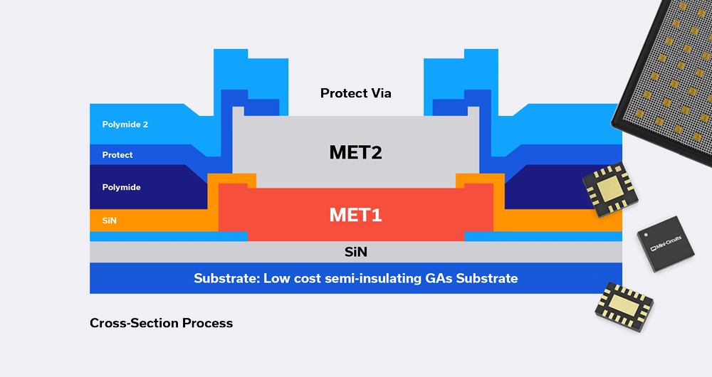
Monolithic Microwave Integrated Circuits (MMICs) with no active elements such as transistors, and containing only passive elements such as resistors, capacitors, inductors, are referred to as Integrated Passive Devices (IPD). These devices do not need DC power to operate, and do not perform frequency conversion as in the case of frequency mixers or frequency multipliers.
What’s the big deal about IPDs? The short answer is they perform vital functions which active elements cannot such as filtering, equalization, balanced-to-unbalanced line conversion (or vice versa) and many more as we will describe later.
Novel MMIC Splitter/Combiner Designs Achieve High Isolation Down to DC
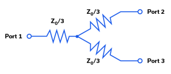
Traditionally, DC power splitter / combiner circuits are implemented with resistors. A simple resistive power splitter / combiner circuit schematic is shown in Figure 1. If Z0 = 50W, and ports 2 and 3 are terminated in 50W, then port 1 is matched to 50W as well, so Z0 / 3 = 16.7W. Resistive power splitter / combiner circuits typically have poor isolation between ports at DC and over frequency.
Mesh Network Simulators for Wireless Device Testing
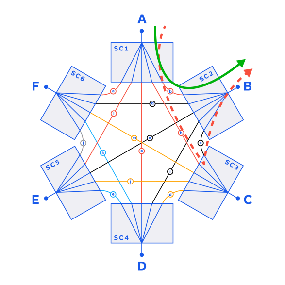
A mesh network is a wireless network architecture in which three or more devices, also called nodes, are all connected to each other. Every node in the mesh network is able to communicate with some or all of the other nodes in the network. This type of architecture is distinct from traditional “hub and spoke” networks in which all devices connect to a central hub through which they communicate with other devices. In the real world, nodes can be wireless routers, cellular handsets, personal computers or any other device capable of sending and receiving signals. Home Wi-Fi networks, local area networking, military and public safety communications are all examples of applications where mesh networks are commonly employed.
A Primer on RF Semiconductors (MMICs)
A Primer on RF Semiconductors (MMICs) Radhakrishna Setty, Technical Advisor Introduction Semiconductors are ubiquitous in modern society. In addition to microprocessors for computing technologies, they are used in practically every active wireless communications system including cell phone towers, cell phones, radars and satellites to name a few. Mini-Circuits designs and produces several semiconductor-based (MMIC) components […]
Extending the Performance and Frequency Envelope for QFN Packaging Technology

High-performance, millimeter-wave (mmW) Monolithic Microwave Integrated Circuit (MMIC) products and cost-effective surface mount lead-frame-based packaging typically don’t come up in the same conversation, and for good reason. Just two to three years ago, it was difficult to conceive of operating at frequencies above 20 GHz without considering an expensive, open cavity, High Temperature Co-fired Ceramic (HTCC) package or resorting to more bespoke chip and wire assemblies.
Understanding Power Splitter/Combiner Power Handling with Coherent and Non-Coherent Signals

A Power Splitter/Combiner is a passive device that can be used for two reciprocal functions: a single signal may be divided into multiple outputs, or in the opposite direction, multiple input signals are combined into a single output. In case of an N-port splitter, the input signal will be divided into N output ports. When used as an N-port combiner, the N inputs will be combined into an output signal from a single port.
מפצלי הספק להתקנה משטחית מגיעים ל- 26.5 ג’יגה הרץ
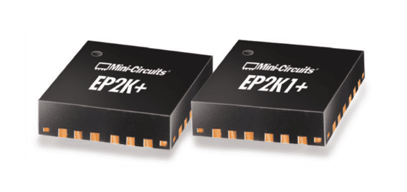
חלוקה של אותות ת”ר (RF) וגלי מיקרו על פני מעגלים ומערכות לתדירות גבוהה מסתמכת במידה רבה מאוד על מפצלי/ מסכמי הספק. מאחר שמגמות התכנון המודרניות מכווצות רכיבים כמו מפצלי/ מסכמי הספק לממדים שקטנים והולכים כל הזמן, בפני אנשי התכנון עומד אתגר משמעותי: כיצד אפשר לנהל רמות סבירות של הספק אותות מבלי לשאת בתוצאות של חום שקשה לפזרו בתוך מעגל או בתכנון המערכת.


