Fully Non-Blocking (Full Fan-Out) RF Switch Matrices

The first two articles in this series established that blocking switch matrices use switches to allow one-to-one connections between input and output ports, while non-blocking switch matrices use splitter/combiners on either the input our output ports to allow one-to-many or many-to-one connections. In this article, we’ll examine the fully non-blocking or “full fan-out” configuration in which all inputs are connected simultaneously to all outputs via splitter/combiners, sometimes with programmable attenuation on every path. Features, advantages, applications and examples will be reviewed.
Switch Matrix Configurations
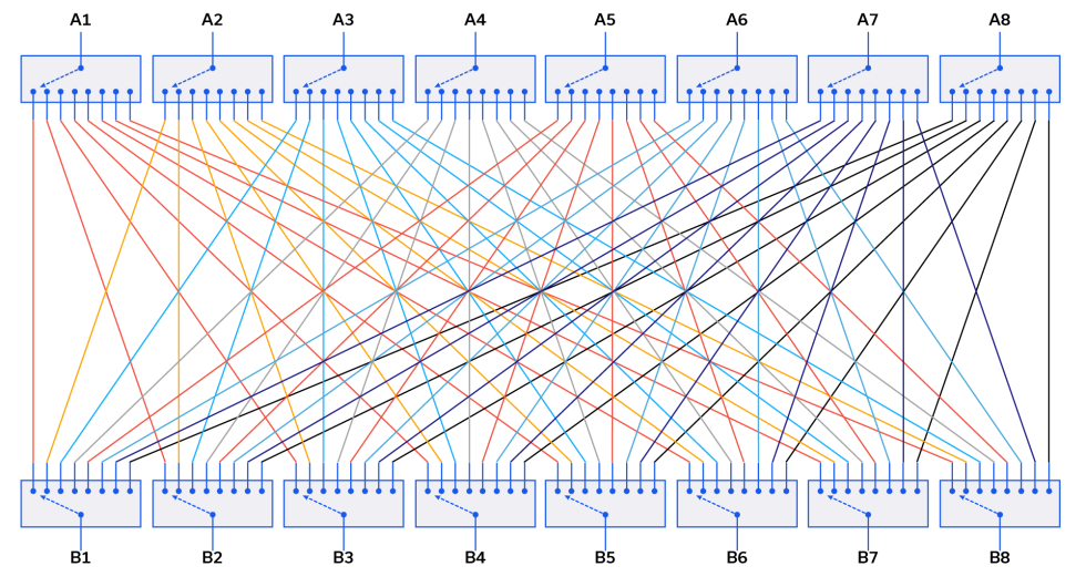
Switch matrices are an essential tool for control of RF signal routing in any environment where there is a recurring need to change how systems interconnect. The addition of Ethernet and USB interfaces with flexible software and APIs (application programming interfaces) makes switch matrices particularly useful in automated test environments, allowing test sequences to be scheduled to run with no user intervention, switching between multiple devices under test (DUT), input / output ports and test equipment.
RF Blocking Switch Matrices

Blocking switch matrices are constructed using switches on the inputs and outputs, as shown in Figure 1. They are called “blocking” because once a path is set between any pair of ports, those 2 ports are not available (blocked) for use by any other path. Multiple paths can be active in parallel, up to the number of input ports or the number of output ports (whichever is fewer), with each path connecting a different pair of ports.
RF Non-Blocking Switch Matrices
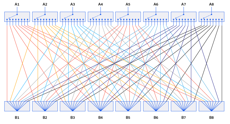
Non-blocking switch matrices are constructed using switches on one set of ports and passive splitter / combiners on the other. They are referred to as non-blocking (sometimes partially non-blocking) since the splitter / combiner component allows a single port to be connected concurrently to multiple ports on the opposite side. Hence the path is not blocking any other ports from connecting, as would be the case with a blocking switch matrix.
Non-blocking matrices are often characterized as either fan-in or fan-out depending on the orientation of the splitter / combiners relative to the input ports.
Mini-Circuits Test Equipment Adapts to Your Changing Needs
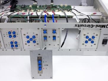
Mini-Circuits ZTM-series modular test system adapts to your changing needs. The system is designed with complete flexibility to replace old hardware and swap out one component for another without returning equipment to the factory for service. The company’s hand-flex cables can be used to connect hundreds of possible routing configurations.
מטריצות מיתוג מסדר גבוה מקילות את ביצוע הבדיקות בתשתיות רשת
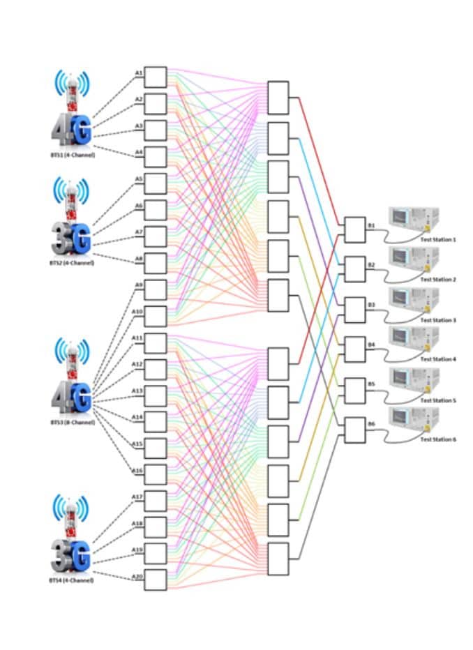
הבדיקה של תשתית רשת סלולרית כרוכה לא פעם באיסוף נתונים מעשרות – אפילו מאות – תחנות בסיס (BTS) בתוך סביבת בדיקה. הנפח והמורכבות של תעבורת האותות במערכות הבדיקה האלו עם ריבוי התקנים וריבוי משתמשים, דורשים יכולת הולמת לצורך ניתוב אותות בין תחנות הבסיס ותחנות הבדיקה. על מנת להוריד עלויות ולשפר את היעילות של מערכות בדיקה לנפחים גדולים, חברת Mini–Circuits, בשיתוף עם לקוחות, פיתחה קו של מטריצות מיתוג שתומך במגוון של תצורות מיתוג ושיטות בקרה. מאמר זה מציג מקרה לדוגמה של מטריצת מיתוג לא חוסמת בגודל 20 x 6 עם גישה מלאה, המשמשת להקלת ניתוב אותות במערכת בדיקה של רשתות סלולריות עם הרחבות ליישומים נוספים.
High-Order Switch Matrices Facilitate Network Infrastructure Testing

Testing cellular network infrastructure often requires measurement and data collection from dozens – even hundreds – of base stations (BTS) within a test environment. The volume and complexity of signal traffic in these multi-device, multi-user test systems necessitates commensurate capability for routing signals between base stations and test stations. By partnering with customers to lower costs and improve efficiency in high-volume test systems, Mini-Circuits has developed a line of high-order switch matrices supporting a wide variety of switching configurations and control methods. This article will present a case study of a 20 x 6 non-blocking, full access switch matrix used to facilitate signal routing in a cellular network test system with extensions for other applications.
שימוש במטריצות מיתוג של Mini-Circuits ביישומי בדיקה של מערכות טלוויזיה בכבלים ל- Ω75
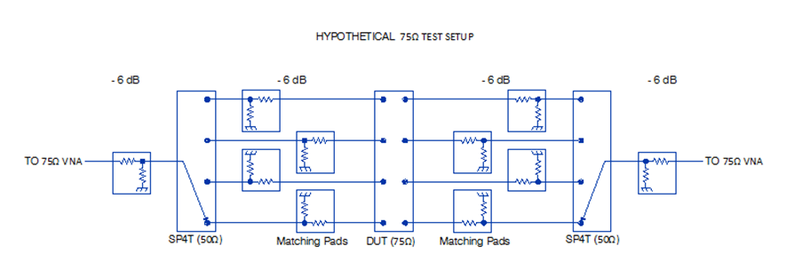
ציוד שפועל ב- Ω75 שמשמש לעתים קרובות ביישומים של טלוויזיה בכבלים (CATV), מהווה נישה קטנה בתחום הנרחב יותר שמשתמש ב- Ω50. אמנם פריטי ציוד ייעודיים ל- Ω75 קיימים, אך הזמינות שלהם ואפשרויות היישום שלהם לדרישות בדיקה אחרות הן מוגבלות; רוב פריטי ציוד הרב תכליתיים שמשמשים לבדיקה ולמדידה מתוכננים לשימוש ב- Ω50. לכן, לא קל לבנות מערכי בדיקה עם ציוד ייעודי ל- Ω75 בלבד..
Using Mini-Circuits Switch Matrices in 75Ω CATV Test Applications

The 75Ω equipment often used in CATV applications occupies a small enclave of a largely 50Ω world. Although dedicated 75Ω equipment does exist, its availability and its applicability to other test needs are limited; most general-purpose test and measurement equipment is designed for 50Ω use. Because of this, it can be difficult to create test setups entirely out of dedicated 75Ω test equipment.


