Peak and RMS RF Power Detectors for High-Frequency Signal Measurement

Power detectors are widely used RF components that convert an RF input signal into an output DC voltage proportional to the RF input power. Power detectors are useful for a number of applications that include automatic gain control circuits, transmit antenna power monitoring, protecting sensitive circuits from pulses and power spikes as well as a wide range of test and measurement applications. Mini-Circuits has developed different types of high frequency, high accuracy power detectors for these applications. These power detector designs have overcome design challenges at mmW frequencies to enable product features that provide market-leading performance for the price point. These design challenges include improving the input and output matching of the detectors over a wide frequency range in the specified product housing that enables extended dynamic range performance over the operating frequency range compared to competitive models. This article will provide an overview of the different types of power detectors and some of the common applications each is best suited for. Specific use cases for measurement setups will be also presented for each type of detector.
How to save time with Programmable Attenuators
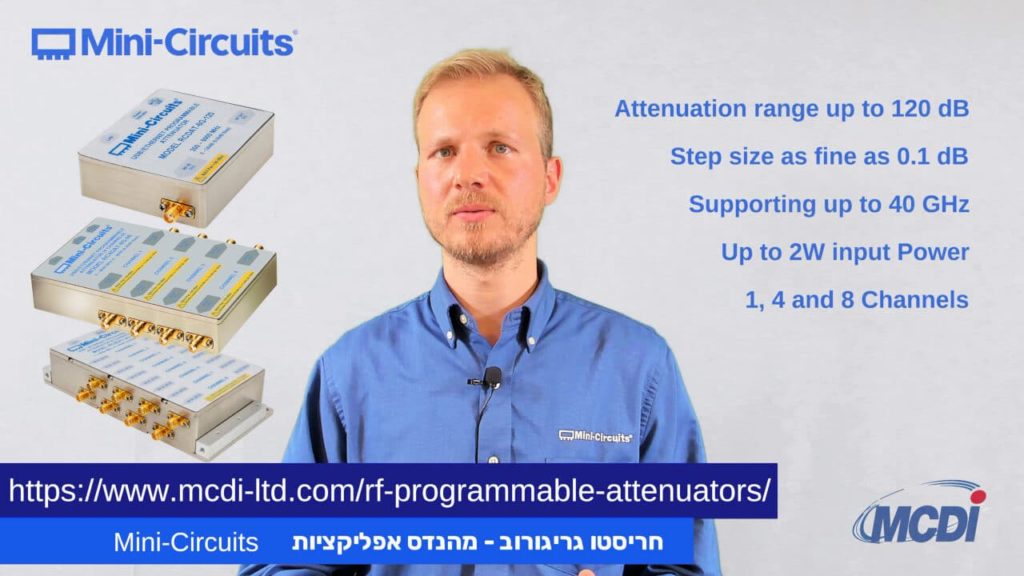
How to save time with Programmable Attenuators Hristo Grigorov – Applications Engineer, Mini-Circuits Israel – MCDI Performing sensitivity tests on RF receivers can be challenging, time-consuming, and prone to issues using the traditional method. To create the sensitivity test setup, you will usually need to create a physical separation between the transmitter and the receiver. […]
Understanding RF Power Amplifier Classes
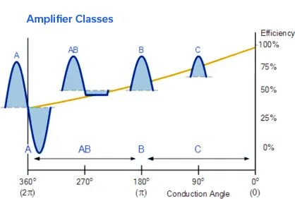
Power amplifiers (PAs) boost input signals using different amplification schemes depending upon application requirements and the nature of the signals to be boosted. Signals may be continuous wave (CW) or many forms of pulsed waveforms, with different pulse widths and duty cycles. Different signal types have different amplification needs in terms of output power, gain, efficiency, linearity, and other performance parameters.
Extending the Performance and Frequency Envelope for QFN Packaging Technology

High-performance, millimeter-wave (mmW) Monolithic Microwave Integrated Circuit (MMIC) products and cost-effective surface mount lead-frame-based packaging typically don’t come up in the same conversation, and for good reason. Just two to three years ago, it was difficult to conceive of operating at frequencies above 20 GHz without considering an expensive, open cavity, High Temperature Co-fired Ceramic (HTCC) package or resorting to more bespoke chip and wire assemblies.
Choosing the Right RF Coaxial Cable Assembly for Your Application
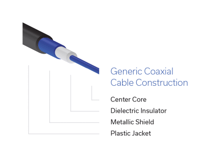
Selecting the right RF/microwave cable assembly can be a confusing task considering the variety of products on the market and the multiple characteristics of each. Adding to the challenge, many products don’t lend themselves to a straightforward, “spreadsheet” comparison. This guide was written to go beyond the spec sheet and help you find the right cable for your needs more quickly and more knowledgeably. We will review the different categories of RF cables and their attributes and provide some guidelines on how to prioritize parameters for your application. Note that we omitted fundamental RF theory because much has been written on that subject and this is meant to be a practical resource for engineers in the field rather than a study guide. We also omitted corrugated and CATV coaxial cable as those are typically used for niche applications.
Reflectionless Filters Minimize Switching Transients in Wideband ADCs
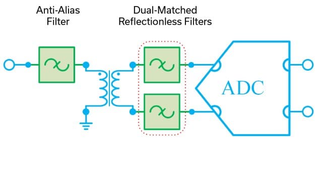
Designers are finding new techniques to improve system performance with Mini-Circuits’ patented reflectionless filters all the time. Among these, supplementing anti-alias filters in wideband ADCs to minimize the effect of switching transients has emerged as a popular use case.
Directional Couplers: Their Operation and Application

Directional couplers are important devices in RF systems. Their ability to sample either the forward or reverse direction of signal propagation allows a wide range of applications in test, measurement, monitoring, feedback and control. This note should help system designers understand the function, architecture and performance of the coupler, to select a suitable type for their particular application.
Understanding Power Splitter/Combiner Power Handling with Coherent and Non-Coherent Signals

A Power Splitter/Combiner is a passive device that can be used for two reciprocal functions: a single signal may be divided into multiple outputs, or in the opposite direction, multiple input signals are combined into a single output. In case of an N-port splitter, the input signal will be divided into N output ports. When used as an N-port combiner, the N inputs will be combined into an output signal from a single port.
Combining MMIC Reflectionless Filters to Create Ultra-Wideband (UWB) Bandpass Filters
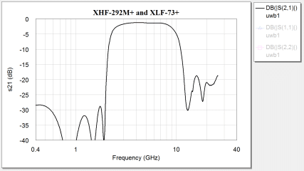
Ultra-Wideband (UWB) radio is defined as any RF technology utilizing a bandwidth of greater than ¼ the center frequency or a bandwidth greater than 500 MHz [1] [2]. While UWB has been a known technology since the end of the nineteenth century, restrictions on transmission to prevent interference with narrow-band, continuous wave signals have limited its applications to defense and relatively few specially licensed operators [1]. In 2002, the FCC opened the 3.1 to 10.6 GHz band for commercial applications of Ultra-Wideband technology, and since then UWB has become a focus of academic study and industry research for a promising variety of emerging applications. To prevent interference with neighboring spectrum allocations like GPS at 1.6 GHz, the FCC has imposed specific rules for indoor and outdoor transmission of UWB signals, limiting transmissions in the permitted frequency range to power levels of -41 dBm/MHz or less.
פיזור המסתורין מעל שנאי ת”ר חלק 1: דיון למתחילים על תיאוריה, טכנולוגיות ויישומים של שנאים

בעיקרו, שנאי אינו אלא שני נתיבים של מוליכים, או יותר, הקשורים ביניהם בשדה מגנטי משותף. כאשר שטף מגנטי משתנה מתפתח בתוך הליבה, כתוצאה מזרם חילופין שעובר דרך נתיב מוליך אחד, מושרה זרם בנתיב המוליך האחר. זרם מושרה זה יחסי ליחס של הצימוד המגנטי בין שני נתיבי ההולכה. היחס בין הצימוד המגנטי של הנתיבים המוליכים לבין הליבה קובע את המתח המושרה בנתיבי ההולכה הנוספים ומספק טרנספורמציה של העכבה (אימפדאנס) וגם העלאה או הורדה של המתח. אפשר להוסיף נתיבים מוליכים נוספים שכולם יכולים להיות עם יחסי צימוד שונים, על מנת לממש פונקציות שונות, וזו הסיבה ששנאי ת”ר (RF) הם התקנים כה מגוונים ורב-תכליתיים, אשר משמשים באופן נרחב בכל תעשיית הת”ר/ גלי המיקרו.
מימוש נפוץ של שנאי ת”ר מורכב משני חוטים נפרדים, או יותר, מלופפים סביב ליבה מגנטית (או ליבת אוויר במקרה של תדירויות גבוהות), וזו הסיבה ששנאי ת”ר מתוארים לא פעם בתור היחס בין מספר הליפופים או הכריכות.


