Choosing the Right RF Coaxial Cable Assembly for Your Application
Introduction
Selecting the right RF/microwave cable assembly can be a confusing task considering the variety of products on the market and the multiple characteristics of each. Adding to the challenge, many products don’t lend themselves to a straightforward, “spreadsheet” comparison. This guide was written to go beyond the spec sheet and help you find the right cable for your needs more quickly and more knowledgeably. We will review the different categories of RF cables and their attributes and provide some guidelines on how to prioritize parameters for your application. Note that we omitted fundamental RF theory because much has been written on that subject and this is meant to be a practical resource for engineers in the field rather than a study guide. We also omitted corrugated and CATV coaxial cable as those are typically used for niche applications.
A Brief Overview of Coax Types:
All coaxial cable consists of a center conductor surrounded by a dielectric insulator, usually PTFE, an outer metal shield to prevent signal leakage and an outer jacket to protect the inner layers from damage. As we will see, the variations of this structure are many and complex, and it serves the user to understand the various categories of coaxial cable construction and the differences between them.
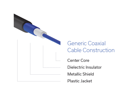
The following is a summary of the different categories of coaxial cables and their attributes:
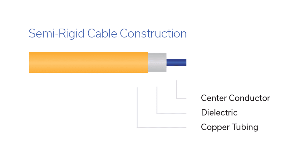
Semi-Rigid (Soft Annealed Copper Tubing)
Semi-rigid coaxial cable assemblies use solid copper tubing as an outer sheath rather than braided sheathing. The solid material offers excellent shielding which is useful in some high-frequency applications, but its main drawback is that it’s not flexible. Semi-rigid cables are typically customized with lengths, bend shapes and connector configurations specified to the customer’s intended use within a unique system layout. They are not intended to be bent or flexed after initial forming, and can be easily damaged during installation.
PROS:
- Efficient RF transmission
- Highly shielded
- Tight bend radius possible
- Good return loss (when the assembly is built correctly)
- Large supplier base for assemblies (but limited number of cable makers)
- Large variety of connectors including crimp, clamp and solder attachments
- Four basic, 50Ω sizes: 0.047”, 0.086”, 0.141”, 0.250” (086 and 141 are the most popular)
- Tin plated copper, tin plated aluminum, and low loss versions available but far less popular
- Smaller diameters suitable through 40 GHz or higher
CONS:
- Must be custom-built
- Assembly is dedicated to each position in the system. Not versatile.
- Requires bend-shape drawings (engineering and drafting time)
- Cable is not flexible
- Supplier may require NRE/tooling charge
- Poor soldering process can cause cracked solder joints at installation
- Many suppliers take process shortcuts that can result in latent field failures
Mini-Circuits does not offer semi-rigid cables due to their inherent cost and lack of versatility. Alternative cable types for interconnect applications have achieved outstanding performance with better overall value and versatility. See tin-soaked cable below.
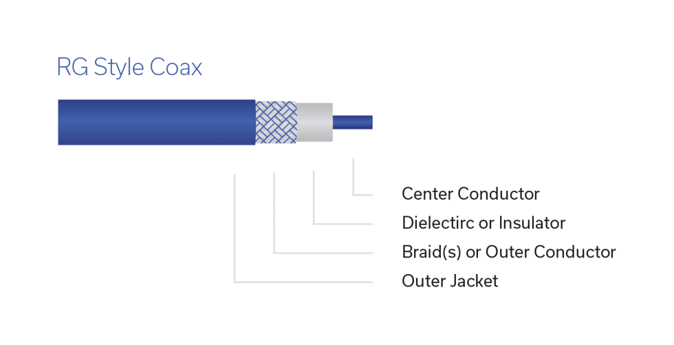
Braided Flexible Coax (RG Style)
“RG” style (for “Radio Guide”) cables use metal braided outer shield rather than solid tubing used in semi-rigid cables. This gives them greater flexibility and resilience making them suitable for re-use in various bend shapes and comparatively more affordable than semi-rigid designs. RG style cables can be manufactured faster than more sophisticated types of braided flexible cable (see high-performance braided flexible coax below), which lowers cost and lead time. Conductor, dielectric and shielding types vary widely within this category, but in general, braided shielding is inherently lossier than solid tubing, resulting in greater attenuation and lower maximum frequency ratings, typically topping out between 3 and 6 GHz.
PROS:
- Wide variety (many cable and assembly suppliers)
- Does not require bend-shape drawings
- Re-bendable, reasonable flex life
- Low unit price, shorter lead times
- Wide variety of connector options depending on the cable including crimp, clamp and direct solder
CONS:
- Less shielding than semi-rigid
- Slightly higher attenuation than similar size semi-rigid
- Can have inconsistent performance between lots or suppliers
- Not spec’d for use above approximately 6 GHz
- Poor assembly techniques and strain relief often result in early connector attachment failure.
High-Performance Braided Flexible Coax
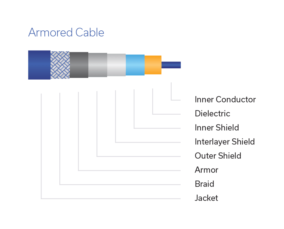
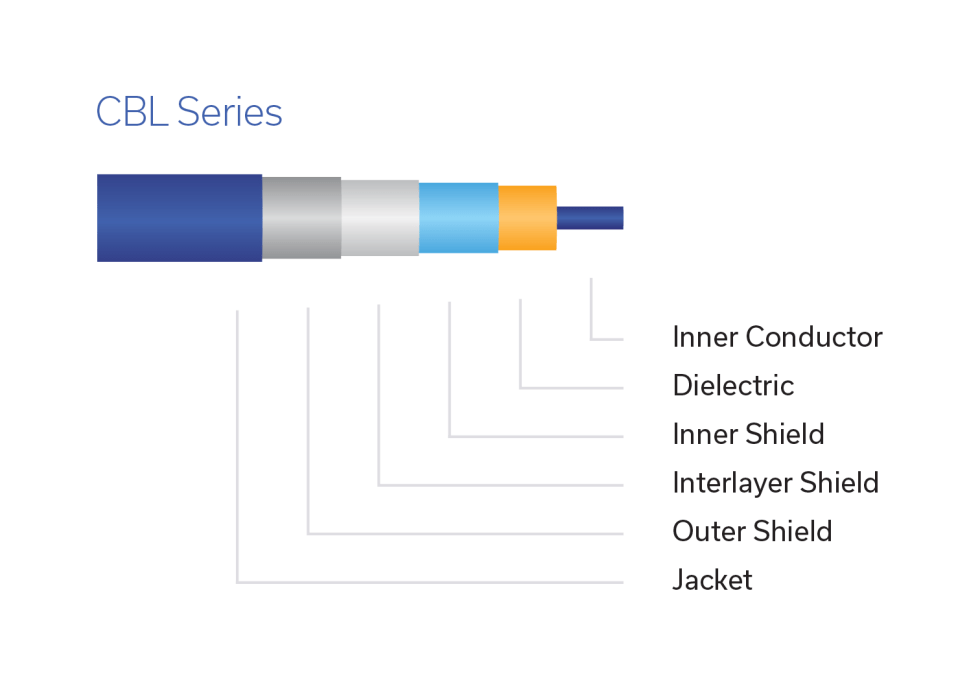
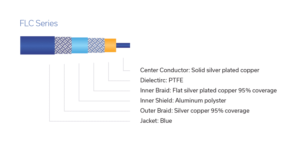
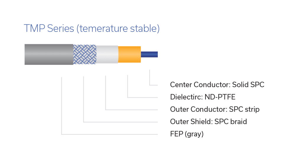
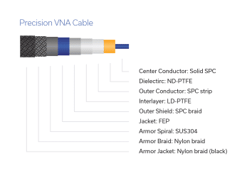
With more advanced cable design, material selection and manufacturing processes, Mini-Circuits has achieved outstanding high-frequency performance with braided flexible cable construction. These high-performance cable assemblies are specified at a minimum of 18 GHz and extend up to 67 GHz while retaining the flexibility and versatility of a braided, flexible coaxial cable. Mini-Circuits’ selection of high-performance braided flexible cables includes models designed and specified for phase stability vs. bend, temperature stability and more. Figures 4 through 8 below several different variants of this cable type designed for different applications and operating environments.
Examples of some of Mini-Circuits’ high-performance braided flexible coaxial cables are shown in Figures 4-8 below.
PROS:
- Wide variety designed to meet specific technical challenges
- Highly shielded
- Very good return loss through 67 GHz
- Long flex life
- RF stable performance with flexure
- Low loss options
CONS:
- More expensive than semi-rigid or RG flexible coax, longer lead times
- More limited cable and assembly supplier base
- Many cables only available as assemblies
- May have a more limited bend radius (more easily degraded from handling abuse)
- Typically requires high assembly skill level to derive the best performance
- More limited connector availability
Tin-Soaked Cable (Mini-Circuits HandFlex®)
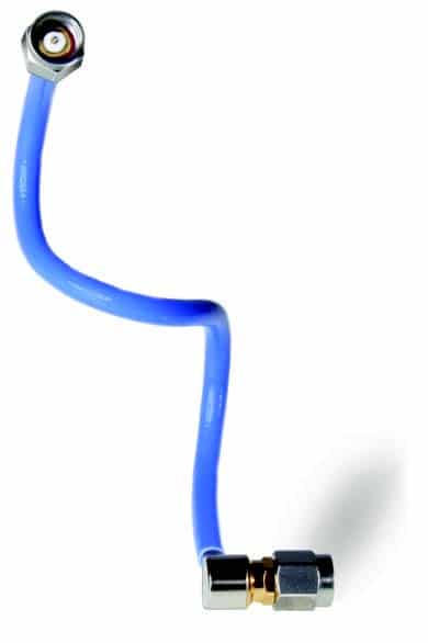
Mini-Circuits’ HandFlex® interconnect cables are built with a tin-soaked copper braid outer shield. These cables offer both flexibility and outstanding performance up to 40 GHz. They also retain their shape after bending, which makes them an excellent substitute for semi-rigid interconnect cables without the need for custom bending. Their hand formability also makes them easier to install in tight spaces with less risk of damage to the cable or connector interface.
PROS:
- A true hybrid of semi-rigid and braided flexible coax with some attributes of both
- Shielding and transmission efficiency similar to semi-rigid
- Somewhat re-bendable
- Does not require bend-shape drawings
- Very good return loss
- Attenuation similar to semi-rigid
- Cost-effective, off-the-shelf delivery or short lead times
- Available in 0.047”, 0.086”, (both through 40 GHz) and 0.141” (to 26.5 GHz)
- Popular connector options. Direct solder only.
- Low loss and jacketed versions available
CONS:
- Connector attachment can be an area of weakness
- Susceptible to damage/degradation from overly aggressive bending
Connector Types and Attachment Methods:
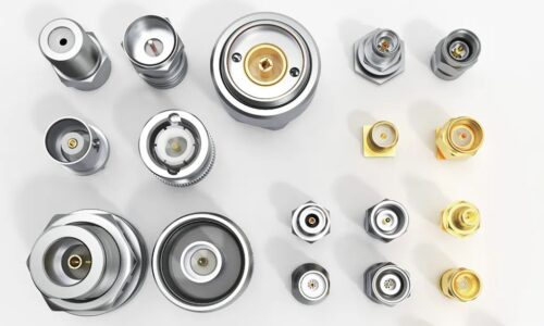
Connectors should be chosen according to the frequency requirements of the application and connector types of the equipment at the input and output of the cable. The chart below shows the most popular connector series and corresponding frequency limits for each.
| Connector Series | Frequency Limit |
| F-Type (75Ω) | 1 GHz |
| BNC | 4 GHz |
| MMCX (Micro-Miniature CoaXial) | 6 GHz |
| N-Type | 11 GHz |
| SMA | 24 GHz |
| SMP (Snap-On) | 25 GHz |
| 3.5 mm | 34 GHz |
| 2.92 mm | 40 GHz |
| 2.4 mm | 50 GHz |
| 1.85 mm | 67 GHz |
| 1 mm | 110 GHz |
Generally speaking, a connector should be chosen for the cable assembly with a center contact and dielectric that have similar diameters to that of the cable center conductor and dielectric. Assuming the attachment process is done correctly, matching sizes results in the optimum return loss.
Connectors are usually attached to the cable in one of three ways: crimp, clamp or solder/clamp and direct solder. A general understanding of the different assembly helps the user evaluate the performance and reliability of a given cable.
Crimp:
While occasionally used on semi-rigid cables, crimp connectors are popular for lower frequency, RG cables. Crimp attachments require less labor but may require specialized crimping tools. They are best used on cables that are not handled frequently. Surprisingly, many suppliers opt to use crimp attachments on test cables, which is not appropriate and affects reliability. An assembly marketed as a test cable with crimp attachments should raise questions about quality in the user’s mind.
Clamp or Solder/Clamp:
Clamp or solder/clamp attachments are used more often in cable designs for military and aerospace applications. They are much more expensive and complicated to assemble, but far more reliable than crimp and will not result in latent cracked solder joints. Mini-Circuits uses solder/clamp on its CBL, ULC and other series of test cables for superior reliability.
Direct Solder:
This method is very popular for semi-rigid and hand formable (e.g. Mini-Circuits HandFlex®) cable. Direct solder connectors ironically are the lowest cost but are also the highest performance because they are simple and result in fewer RF discontinuities. Within this category there are separate and no-separate contact designs. Separate contact designs employ a variety of captivation methods depending on the maker including barb, epoxy, and mechanical shoulders. Soldering skill and technique is very important to the performance and reliability of the finished product. Lack of skill and proper technique in the manufacturing process will almost always result in cold solder joints or cracked solder joints either immediately or later in the field. Field failures can obviously be expensive to remedy.
Identifying Your Application Requirements
With the various coaxial cable types, connector options and their respective attributes in mind, consider the specific operating requirements of the application as the logical starting point.
The best way to optimize system performance and keep costs under control is to address the cable requirements early in system design. Include mechanical and packaging engineers in the decision-making process if the task of selecting interconnects will fall to them. Often, fitting everything into a given space without compromising system performance can be challenging. With deadlines looming, options can become limited and interconnect costs can rise.
To start identifying and prioritizing your desired parameters, answer at least these questions:
- Is the cable installed and never handled again (AKA “in-the-box”) or is it handled frequently as with a test cable?
- Will it only need to exhibit the defined performance at rest or while in motion such as with an antenna gimbal cable?
- Will it need to maintain its RF characteristics at extreme temperatures such as in a temp chamber?
- Will the cable be subjected to extreme environmental conditions like high altitude, humidity and vibration such as in flight, or is it a benign environment like a design lab (RF breadboard)?
- Is the required connector series appropriate for the application? Are they common or very unusual for the size of cable being considered?
Answering these questions will help define the ideal cable category and better narrow the search to specific cables and suitable suppliers.
A Simple Framework for Your Cable Search:
Even in ideal circumstances, the choice of a coaxial cable will usually require compromise, so Mini-Circuits suggests users first parse their needs according to the following framework:
- Need-to-have: attributes that cannot be compromised.
- Nice-to-have: attributes that are desirable, but are not necessarily mandatory.
These characteristics can then further be organized into four categories according to their key attributes:
- RF performance
- Materials/construction
- Connector series
- Mechanical / environmental operating conditions.
Rule of thumb:
A cable that achieves the first three need-to-have characteristics will likely be the cable or assembly of choice at the best price. Continued investigation with suppliers in an attempt to include additional need-to-have and nice-to-have characteristics will reveal if there is a price trade off, which may help you make a more informed decision.
Sometimes it is impossible to allow certain trade-offs above in system design. In those instances, high performance coax may be the only solution. For example, a supplier may be able to stay within the loss budget and/or cable diameter constraints by using high performance coax at greater cost. Or perhaps other goals can be achieved simultaneously. There is no free lunch, however, and achieving more electrical, mechanical and environmental requirements usually involves higher prices, more limited connector selection and/or longer lead times.
Performance Parameters and Common Tradeoffs
For ease of viewing, the most common performance parameters for RF coax cables are summarized in the chart below:
Electrical
- Frequency range
- Attenuation (max loss)
- Power handling
- RF stability
- Shielding
- Return loss / VSWR
Mechanical
- Outside diameter
- Flexibility (min. bend radius)
- Flex life
- Weight
- Dielectric material
- Connector series
Environmental
- Temperature range
- Humidity
- Vibration
- Resistance to solvents/UV
- Outgassing
- Altitude
Impedance is a compromise between power handing and attenuation and changed by varying the ratio of inner & outer conductor sizes. We do not list impedance in the table above because the majority of communications systems are 50Ω, while 75Ω is standard for CATV systems. Mini-Circuits sells both 50Ω 75Ω test cables.
Cable diameter affects many other attributes, which is why it’s usually at the top of the list in the selection process. Increasing the outer diameter of a cable can reduce its insertion loss, increase power handling and termination strength. However, wider cable diameter also results in lower maximum frequency rating, increase in minimum bend radius, less flexibility and more weight. Wider cable diameters also limit choice of connector types, which has additional consequences outlined in greater detail below.
Bend radius, flexibility and flex life all depend on cable diameter, so customers with strict requirements for these factors will gravitate toward cables with smaller diameters. This typically means sacrificing power handling and insertion loss performance to some extent.
Rule of thumb:
- The one-time minimum bend radius of a cable is 5x the outside diameter of the cable.
- The minimum re-bendable radius of a cable is 10x the outside diameter.
- There is some variation in this rule depending on the frequency and tolerance for RF degradation after bending.
Power handling increases with cable diameter. Users with high power requirements may therefore need to sacrifice cable flexibility and high frequency performance. Additionally, smaller connector types and poor return loss that result from low quality connector attachment can reduce power handling. Power handling also degrades at high altitude and high temperature, so users building systems for these operating conditions should ensure the cables they choose have been properly qualified.
Operating frequency range is typically a hard requirement defined by the bandwidth of the system, but frequency determines a number of other factors system designers need to weigh. For example, cable attenuation is a function of frequency: the higher the frequency, the leakier the signal. Better return loss is also more difficult to achieve as frequency increases. Frequency dependent losses can be mitigated by adding shielding; triple shielded cable is often used to achieve similar isolation to that of semi-rigid cables. More shielding typically requires additional outer conductor layers which adds complexity to the production process and cost to the end product.
RF stability depends on several factors, including whether the cable will be subject to regular handling and bending (in the lab) or fixed in placed. Most cables include manufacturer ratings on minimum bend radius and total number of flex cycles before RF performance starts to degrade. Learn more about how bending affects phase stability here. RF stability is also affected by a number of environmental factors such as temperature, which becomes important when cables are used in temperature chambers for high temperature operating life (HTOL) testing, or in assembled systems where extreme temperatures are expected. Mini-Circuits offers cables specially designed for phase stability versus bend and temperature stable cables.
Other environmental factors such as UV protection, resistance to solvents and outgassing are highly specialized requirements for niche applications demanding careful selection of all materials including the cable jacket. For outgassing concerns, the cable construction, the glue used in the heat shrink strain relief, gasket materials and epoxies are all specialized materials. Space applications will also require vented connectors with highly specialized internal designs and attachment processes to prevent voltage breakdown. These are not trivial challenges to overcome and RG cable will almost never suffice.
Passive intermodulation (PIM) are harmonics created by non-linearity in RF connections or devices, which can result in degradation of received signal. Low PIM cable assemblies require cable and connectors built specially to reduce PIM. Historically corrugated cable (not discussed here) offers the best PIM performance but today some braided coax comes close to corrugated.
Conclusion
As we’ve seen, choosing the right cable for a given application involves a number of complex electrical, mechanical and environmental variables. With a solid foundation on the different types of coaxial cable construction, RF connectors and attachment methods, key performance parameters and common tradeoffs, you’ll be better equipped to make a more informed decision.
Mini-Circuits online cable search tool provides a good starting place to narrow down your search by cable type, diameter, connector configuration and other factors. Our off-the-shelf selection includes over 375 models, but we often support customers with custom options including unjacketed cables, special connector requirements and more. If you don’t see what you need on our website, contact our engineers to discuss a solution for your needs.


