LTCC Filters Enhance Differential Circuit Designs
Differential Signal Processing in Analog-to-Digital Converters (ADCs) and Digital-to-Analog Converters (DACs)
Today’s analog-to-digital converters (ADC) and digital-to-analog converters (DAC) are typically differential circuit designs. Differential circuits provide many advantages over single-ended designs, including common-mode rejection of thermal noise, even order harmonics, and power supply noise and spurs. Additionally, differential circuits allow for half the voltage swing on each output compared to a single-ended design. Discrete transceivers on the other hand are often designed with single-ended, 50Ω matched components such as low noise amplifiers (LNAs), mixers and IF gain amplifiers. To interface with a differential ADCs or DACs, a single-ended-to-differential, or differential-to-single-ended, a transformer or balun is needed.
For an ADC, anti-aliasing filtering at the input is an important function to filter out wideband thermal noise and prevent it from folding into the first Nyquist region of the ADC (defined in frequency as half of the ADC sample rate). If an amplifier drives the ADC with a wide bandwidth, the amplifier’s output noise beyond the first Nyquist region will fold into the first Nyquist region through the ADC sampling process and add to the noise floor of the ADC, which can degrade the overall noise performance of the signal chain. An anti-alias filter placed after the amplifier and before the ADC input will limit the amplifier’s bandwidth, and thus its output noise contribution to the ADC noise floor. An anti-aliasing filter also filters out wideband spurs generated in the receiver that would otherwise alias in the first Nyquist zone of the ADC. Similarly, the output differential filter for a DAC provides filtering of wideband noise and spurs generated in the DAC.
For both the ADC and DAC filters, the preferred design is a differential low pass filter (LPF) to screen out the noise and spurs. The typical board area taken up by surface mount components used in filter construction can be significant, and the industry is driving towards the perpetual miniaturization of all components. Mini-Circuits has answered the call by developing a family of dual/differential filter products that enable that miniaturization while supporting the need for differential lines at ADC inputs and DAC outputs.
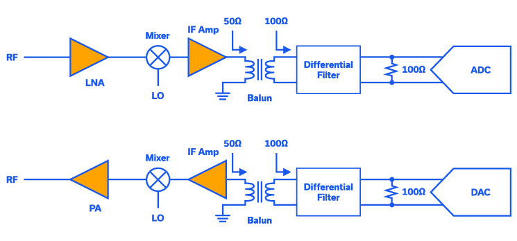
Considering the benefits of differential signaling described above, it is desirable to maintain differential signaling as far back in the signal chain as possible for a receiver, and as far forward as possible for a transmitter. A notional implementation of a transceiver is shown in Figure 1 based on these assumptions. The differential filter can be composed of either 2 single-ended filters, each matched to 50W, or a single truly differential filter matched to 100W differentially. In either case, to go from single-ended domain to differential domain, and provide a matching impedance, an impedance transformation is required. This is typically done using a balun, as shown in Figure 1. It should be noted that the balun can be used in several locations in the transceiver chain to create the differential signal. In this case the balun is shown adjacent to the anti-aliasing filter emphasize the benefits of using a differential filter.
Since single-ended components are matched to 50Ω, and the differential filter input impedance is matched to 100Ω, a balun is required to transform impedance and split the signal from single-ended to differential. In Figure 1, the balun and the differential filter are shown as two separate discrete surface mount (SMT) components. Mini-Circuits has developed a family of integrated balun-filter products that combine these functions into one component, simplifying this implementation and enabling a significant reduction in board space.
Benefits of Integrated Differential Filters
There are many benefits to integrated differential filters. Whether the differential filter is constructed using two (dual) single-ended filters, or one fully differential filter, the ability to integrate the passive components on the same substrate provides some important performance advantages. As described above, one benefit of differential design is common-mode rejection. Others include gain and phase matching between the two single-ended signals. Ideally, each of the two single-ended signal paths has the same gain and are 180 degrees out of phase. Gain and phase unbalances in the differential signal path will result in degraded rejection of common-mode noise, spurs, and even order harmonics. A fully integrated differential filter will allow for optimum component matching which will, in turn, minimize these errors in the two signal paths.
Two single-ended discrete filters used for the differential signal path will not have the same benefits of component matching and performance that the fully integrated differential filter will have. Ideally, these differential filters would also have a small footprint to minimize the associated board space required. An additional benefit of an integrated differential filter is that the line lengths for the substrate are short, thereby further reducing gain and phase errors. Mini-Circuits has developed a family of these differential filters that provide all of these benefits using Low Temperature Co-fired Ceramic (LTCC) substrates in small footprint packages ranging from 0805 to 1210.
Benefits of LTCC Technology
Low temperature co-fired ceramics (LTCC) have been a popular technology for surface-mount designs for many years because of its ruggedness, repeatability and low cost. LTCC circuit substrates can be stacked with up to 30 unique layers, combining dielectric and conductor materials fabricated between the different LTCC tape layers. LTCC materials typically have low dielectric loss and a dielectric constant (Dk) ranging from about 5 to 10. Higher Dk values leads to smaller LTCC circuit dimensions. As Dk increases, the capacitance value per unit area increases, contributing to a smaller overall footprint for the implementation of a differential filter.
Tight control of circuit dimensions and dimensional tolerances are required to ensure LTCC designs can perform at millimeter-wave frequencies (which start at 30 GHz with a wavelength of only 10 mm or 0.394 in.). LTCC filters share the performance benefits of a common substrate, including amplitude- and phase-matched filter channels that support differential systems along with the space saving benefits of integrating both filter circuits in a single monolithic structure.
Among the many advantages of LTCC relative to other technologies, LTCC filters are comparatively small. The ability to stack up to 35 layers allows implementation of complex circuit topologies with unparalleled miniaturization. These components are extremely rugged due to their ceramic construction and monolithic structure, and are suitable for extreme environments such as space, cryogenic enclosures, high-vibration and others.
Until recently, LTCC was predominantly used for application bandwidths below about 10 GHz, but recent advances in material systems and circuit topologies have allowed Mini-Circuits to develop filters with bandwidths well into the mmWave range. LTCC accommodates all forms of circuits including lumped, distributed and cavities (SIW), and is therefore suitable for a wide variety of applications from VHF communications to 5G and other emerging high-frequency systems.
From an economic standpoint, LTCC is an ideal technology for designs that need to be scalable for high volume production due to its inherent repeatability and low cost. Mini-Circuits provides production volume versatility from small quantities in the development phase to volumes in the order of thousands and millions at the production stage with relatively low NREs for special designs and short lead times on design and production.
Material and Construction
Economics
Performance
Mini-Circuits LTCC Differential Filter Products
Mini-Circuits has developed a number of LTCC differential filter products available from stock and others available on request. The LFCN-291-1PM+, for example, is a dual low-pass filter capable of differential operation. It has separate single-ended 50Ω input and output ports. The filter structure used for this product is an 8th order Butterworth LPF. It features a wide passband of DC to 290 MHz with a high-rejection (45 dB typ.) and fast roll-off. The stopband extends to 2 GHz. LTCC’s miniaturization capabilities enables the model LFCN-291-1PM+ to pack two single-ended lowpass filters into one 1206 LTCC surface-mount package (Fig. 3). The package has wraparound leads, as shown in Figure 3, for ease of soldering and inspection.
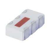
This filter measures only 0.126 × 0.063 × 0.035 in. (3.20 × 1.60 × 0.89 mm) accommodating dense printed-circuit-board (PCB) layouts, while handling as much as 8.5W (+39 dBm) of input signal power. Passband insertion loss is typically only 2.0 dB and no higher than 3.5 dB while the passband VSWR is typically 1.22:1. The dual filters are fabricated on a common LTCC substrate and each single-ended filter is matched to have a 3 dB cutoff frequency of 325 MHz. Stopband rejection is typically 20 dB at 460 MHz and 45 dB from 600 MHz to 2 GHz. The dual lowpass filter maintains consistent performance over an operating temperature range of -55 to +100°C.
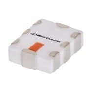
At higher frequencies, Mini-Circuits’ model DLFCV-1600+ is a dual/differential LPF with a passband of DC to 1600 MHz and stopband extending to 10 GHz. The passband insertion loss is typically only 1.5 dB and no more than 2.5 dB. The high roll-off of the filter supports a stopband rejection that is typically 50 dB at 4.9 GHz and typically 25 dB or more to 10 GHz. With a 3-dB cutoff point of 1800 MHz, this is a dual LPF with a sharp transition from passband to stopband for spurious and harmonic rejection of balanced lines in support of a wide range of ADCs and DACs in receiver front ends. It has dual 50Ω input and output ports and is supplied in a compact 1210 ceramic package (Fig. 4) measuring just 0.125 × 0.098 × 0.039 in. (3.20 × 2.50 × 1.00 mm).
Visit the filters page on our website for a complete listing of Mini-Circuits LTCC dual/differential RF filters.
Conclusion
Differential circuits provide effective ways to reduce harmonics and spurious signals in radio front ends. LTCC designs support wideband filters with excellent responses in small component sizes. Through extensive testing and characterization, Mini-Circuits has developed a large library of LTCC-based products that have made it possible to take advantage of LTCC’s capabilities, including miniaturization of dual differential filters and integrated balun-filters. Future Mini-Circuits products will continue to leverage LTCC technology to develop discriminating products in the marketplace.


