Understanding RF Power Amplifier Classes
How Power Amplifier Classes Work
Power amplifiers (PAs) boost input signals using different amplification schemes depending upon application requirements and the nature of the signals to be boosted. Signals may be continuous wave (CW) or many forms of pulsed waveforms, with different pulse widths and duty cycles. Different signal types have different amplification needs in terms of output power, gain, efficiency, linearity, and other performance parameters.
Ideally, a PA operates with high efficiency, so most of its applied power supply is used to boost the amplitude of an input signal, and high linearity, so output power is directly proportional to input power over most of the input power range. In reality, though, designers make tradeoffs between efficiency and linearity depending on the requirements of a given application. Lower efficiency results in power converted to heat in PA semiconductor junctions, which must be dissipated to avoid performance degradation and protect the amplifier and its active devices from overheating. At the same time, poor linearity means the amplifier will operate more in the non-linear region of its power curve, which can create distortion in the form of harmonics and intermodulation products.
Priority depends on the nature of the application and the signals involved. For example, some input signals commonly found in communications systems with amplitude modulation (AM) and/or phase modulation (PM), require maintaining the amplitude and phase relationships at the input of an amplifier through to the higher-amplitude output signals. An amplifier with good linearity preserves the AM and PM relationships. A PA with poor linearity will generate unacceptable levels of intermodulation distortion (IMD) when boosting the multitone signals commonly found in such systems. In other applications such as radar where pulsed signals are used, amplifier efficiency, gain and output power may be more important and high-linearity may not be needed.
Different classes of amplifiers were developed to help users differentiate the various configurations and operating modes that result in different balances of linearity, efficiency, and other parameters. This article explains the basic characteristics and differences between the most common RF amplifier classes (A, AB, B, and C). Real-world examples are examined to illustrate typical performance.
Learn the Alphabet: Differences Between Amplifier Classes
The different amplifier classes are denoted by capital letters, with different configurations from Class-A through Class-T, although the most common configurations are:
- Class-A
- Class-B
- Class-C
- and a hybrid configuration known as Class-AB
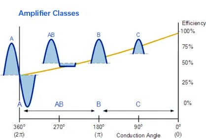
In general, the class of an amplifier refers to the portion of the waveform being amplified for which an amplifier’s transistors are “ON” or in their conduction state. An amplifier with active devices in a full 360° conduction state, or “always on,” will use more power and have less efficiency than an amplifier with the same devices that draw current at only a 180° conduction angle. For a pulsed signal with a short duty cycle, an amplifier with the full device conduction state may not be needed, and an amplifier with high efficiency can help save power applied to the amplifier and improve efficiency.
Class-A Amplifiers
Class-A amplifiers are designed to operate with active devices in full 360° conduction. Its transistors are powered or biased in the “on” state, drawing current and using power 100% of the time. While this amplifier configuration provides very linear performance and the best signal fidelity from input to output, it is also the least efficient of the amplifier classes, with typically less than 50% drain efficiency for the amplifier’s transistors.
Low efficiency translates to higher power consumption than an amplifier with higher efficiency. It also usually means excess heat generated by the active devices must be properly dissipated to maintain performance and expected operating lifetime. Excess heat is usually dissipated using thermally conductive materials such as heat sinks, which add to the size and weight of a design.
Class-A amplifier configurations are used in low-noise amplifiers (LNAs) and other small-signal amplifiers when linearity and low distortion are needed and the signal levels are low enough so that the heat generation due to low amplifier efficiency is not a concern, such as in the input stages of a PA. But for amplifying signals at higher output-power levels, different amplifier configurations are needed.
Class-B Amplifiers
In a Class-B amplifier, only half or 180° of the active devices’ conduction angle is used to save energy and boost efficiency. This can be achieved with the way the active devices are biased on and off. One example of a Class-B amplifier configuration is a “push-pull” amplifier with two transistors, one of which is conducting during the positive portion of an input sinewave signal and the other conducting during the negative portion with the higher-power parts of the boosted sinewaves combined at the output of the amplifier.
Because the active devices in a Class-B amplifier are conducting for half the time of the active devices in a Class-A amplifier, the efficiency of a Class-B amplifier can be much higher than a Class-A amplifier, as high as 75% and typically about 70% compared to the less than 50% efficiency in a Class-A amplifier. But the switching on and off the device conduction angles degrades linearity, as evidenced by higher multitone distortion, such as IMD.
Class-AB Amplifiers
Class-AB amplifiers combine elements of Class-A and Class-B amplifiers to gain the benefits of both. Class-AB amplifier active devices operate with a conduction angle of about 270°, higher than the 180° of Class-B but less than the 360° of Class-A to balance good linearity with high efficiency. The active devices are not fully shut off after their 180° on-cycle, and a small amount of bias energy is applied to effectively achieve the 270° conduction angle, minimizing the crossover distortion that can result from fully shutting off the device (as in a Class-B amplifier). A Class-AB amplifier is capable of linearity approaching that of a Class-A amplifier but with much higher efficiency, typically between 50% and 70% drain efficiency.
Class-C Amplifiers
Class-C amplifiers switch active devices between tuned and untuned modes, operating with low conduction angles of typically less than 90°for higher efficiency than Class-A, B, or AB amplifiers, at typically greater than 80%. They are capable of high output power with high gain but the switching between device operating modes tends towards more nonlinear operation than Class-A, B, or AB amplifiers, making this amplifier class unsuitable for modulated signals.
Additional amplifier classes, such as Class-D, E, F, and G and even proprietary configurations such as Class-T use switching approaches among multiple devices or biasing methods for active devices to achieve high output power levels with high efficiency. Class-D amplifiers, in fact, are more like switches than amplifiers, boosting input signals by means of pulse width modulation (PWM) and reconstructing the switched PWM waveforms back to the amplified versions of the input waveforms at the output of the amplifier. Such nonlinear amplifiers are typically used for digital audio and motor-control applications.
Examples
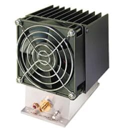
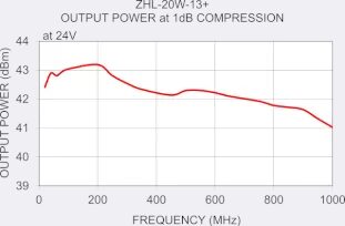
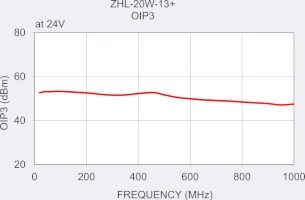
What do different amplifier classes mean in terms of real-world performance? As an example of a Class-A amplifier, model ZHL-20W-13+ is a patented 50Ω PA from Mini-Circuits with integrated shut-off function as protection against overheating (Fig. 2). It provides 20W output power from 20 to 1000 MHz with 50 dB typical gain and ±1.8 dB gain flatness across the full frequency range. A high output third-order intercept point (OIP3) relative to the output power at 1 dB compression (P1dB) is usually one sign of high amplifier linearity, and the typical OIP3 for this Class-A amplifier is +50 dBm with typical P1dB of +39 dBm, indicating very high linearity with low AM-to-AM distortion. The amplifier draws 2.8 A current from a +24-VDC supply.
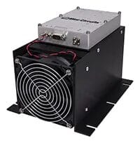
Although not a fair comparison because of its wider frequency range of 20 to 2700 MHz and higher saturated output power of 25W, model ZHL-25W-272+ from Mini-Circuits (Fig. 3) is a good example of a Class-AB amplifier. This model has 50 dB gain across the full frequency range. It provides typical P1dB of +40 dBm with typical OIP3 of +49 dBm, indicating good linearity but not quite the excellent linearity of the model ZHL-20W-13+. However, the power added efficiency (PAE) of this model is 24% while that of the Class-A model above is 15%, indicative of the tradeoff we’d expect to see between the different design classes. The model ZHL-25W-272+ draws 3.5 A current from a +28-VDC supply.
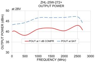
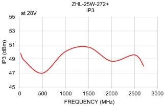
Good linearity (as indicated by high OIP3 relative to P1dB) is possible in a Class-AB amplifier without the high power consumption and lower efficiency required for the somewhat better linearity of a Class-A amplifier. While these are rough comparisons, for amplifiers with different frequency ranges, they show the trends for power consumption/efficiency and linearity for these two amplifier classes. Those trends remain true for a given semiconductor technology, such as silicon (Si) or gallium arsenide (GaAs) transistors but can receive a boost when an amplifier is implemented with a semiconductor technology with enhanced features, such as high-power-density, high-efficiency gallium nitride on silicon carbide (GaN-on-SiC) transistors.
To explore more examples, check out Mini-Circuits full selection of RF amplifiers.


