Understanding RF/Microwave Push-Pull Amplifier Design
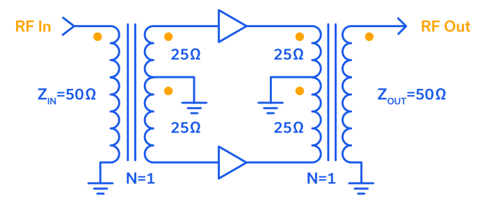
Remarkably, the concept of the push-pull connection spans three centuries. William W. Dean of the Bell Telephone Company of Missouri first described the push-pull-connected telephone transmitter in Patent No. 549,477, dated November 5, 1895.1 Next, Sir John Ambrose Fleming invented the first vacuum tube in 19042 and while Lee De Forest added the grid to Fleming’s “valve” in 1906, calling it the “audion,” it was Fritz Lowenstein in his April 24, 1912 patent application who first discovered that applying a negative bias to the grid of De Forest’s tube turned it into an audio amplifier.
Optimizing Transistor Stages for Different Operating Bandwidths
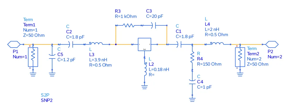
Since their invention by John Bardeen, Walter Brattain and William Shockley at Bell Labs in 1947, transistors have become a defining (if not the defining) feature of the contemporary technology landscape. Electric vehicles can have over 5 billion transistors in a given build, and today’s smartphones more than 10 billion! While their most common and familiar uses reside in the digital world, transistors are an essential element in RF circuits and systems, and while often integrated into more complex, multi-function devices, the simple transistor is still an essential tool in the designer’s toolkit.
Boost Your Knowledge: A Comprehensive Guide to RF Amplifiers – Types and Applications Explained
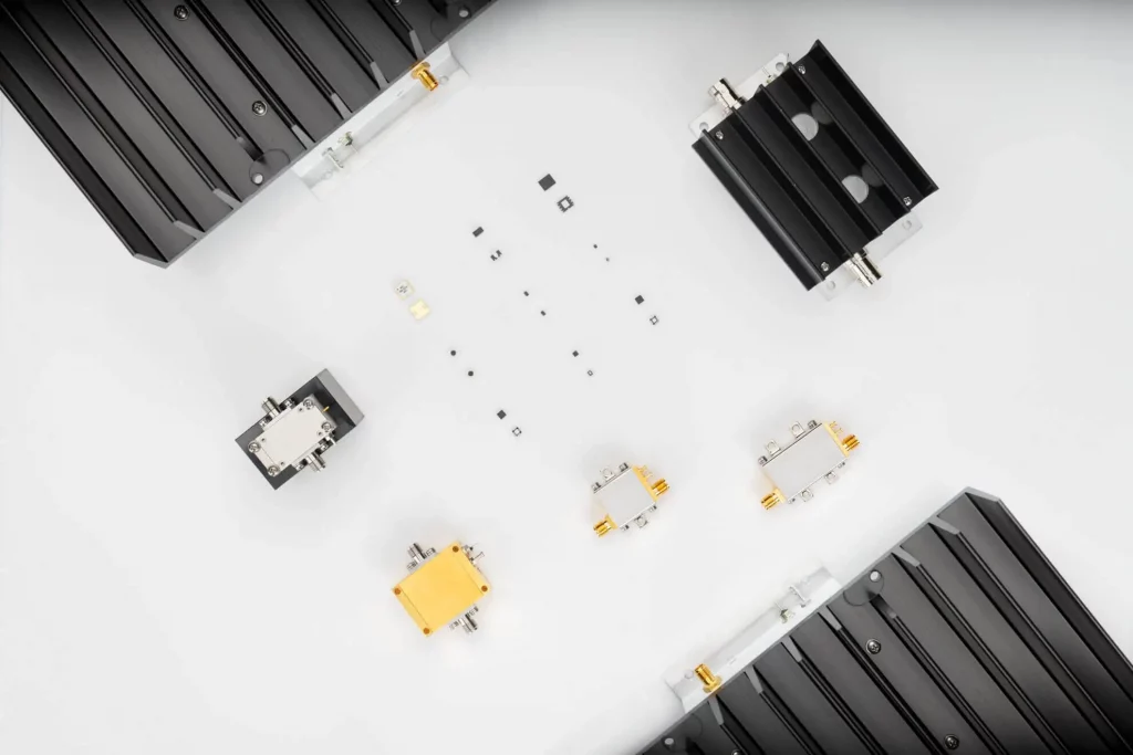
Radio Frequency (RF) amplifiers are electronic components that are used to amplify radio frequency signals. These components can be found in a wide range of applications, including wireless communication systems, television and radio broadcast systems, and medical imaging equipment. RF amplifiers are also used in test and measurement equipment, as well as in radar and satellite communication systems.
There are several different types of RF amplifiers, offering unique characteristics and uses.
RF/Microwave Balanced Amplifiers and Their Applications

A balanced amplifier is the proper term for a pair of devices operated in quadrature phase and combined to amplify a signal. Quadrature simply means that signals incident upon the devices are 90⁰ out-of-phase with one another. The term “quadrature-combined pair” (often shortened to simply “quad-combined pair”) is perhaps just as common as “balanced amplifier,” and both are as identical as “PTFE” is to “Teflon®.”
This article explains the use of quadrature hybrid splitters and combiners (also often called hybrid couplers) in balanced amplifier configurations and the advantages of combining two amplifier devices in this fashion. Two of the most common applications for the balanced amplifier (quad-combined pair) are described by way of example.
Every Block Covered: Cascaded P1dB and IP3 in a 26 GHz 5G Front-End
The goal of this article was to provide students and designers alike with a deeper understanding of the equations behind the cascading of P1dB and IP3 as the system expands to include multiple nonlinear components such as those utilized in the RF, frequency conversion and IF sections of a receiver chain. A 5G RF front end was presented for the 24.25 – 25.1 GHz portion of the 5G n258 frequency band comprised of all SMT parts. Calculated data for linearity parameters was presented for individual components in the signal chain as well as cascaded at each stage. The equations used to calculate those results were provided, and an examples were given showing how to calculate cascaded linearity parameters OP1dB and OIP3 from one stage to the next.
Every Block Covered: Noise and Signal-to-Noise Ratio (SNR) in a 26 GHz 5G Front-End

The 24.25 to 27.5 GHz frequency range is also known as the “wider 26 GHz band” or 5G band n258. The Australian Communications and Media Authority (ACMA) “recognized that the wider 26 GHz millimeter wave (mmWave) band was at the forefront of the delivery of mmWave 5G wireless broadband services globally.”2 Consequently, in April 2021, a major portion of that spectrum was auctioned off to operators, predominantly in the 25.1 to 27.5 GHz frequency range.2 The 24.25 to 24.7 GHz band was identified for indoor use and the 24.7 to 25.1 GHz band for indoor/outdoor use.2 For the purposes of the RF front end in this application note, our focus will be on this lower, 24.25 to 25.1 GHz portion of the Australian 5G frequency range.
Linearity – Cascaded P1dB and IP3 for a Simple Microwave Front-End
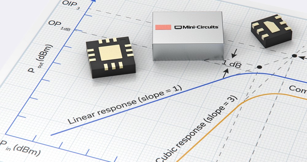
When examining a device data sheet, linearity parameters P1dB and IP3 are straightforward and relatively easy to apply during the design process. Once several components are connected in series in a design, complex equations governing cascaded P1dB and IP3 must be utilized to determine the overall linearity performance of the system or subsystem. The equations utilized to compute P1dB and IP3 provide a means of achieving accurate results in the absence of expensive simulation software. Even though the effect of VSWR interactions between stages is not included when performing the calculations, the results are a good first order approximation of the cascaded performance of the system. The purpose of this application note is to review P1dB and IP3 in general, and to compute these parameters for a basic, three-component RF front end. Other application notes in this series will delve further into the cascading of P1dB and IP3 as the system includes additional nonlinear components such as those utilized in frequency conversion and the accompanying IF components.
Every Block Covered: Noise and Signal-to-Noise Ratio (SNR) in a Simple Microwave Front-End
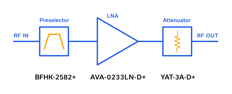
When a technical discussion turns to noise, especially with several cascaded components involved, the calculations and terminology should be straightforward, but often they become more cumbersome than necessary. Signal-to-noise ratio (SNR) is another parameter that should be routinely calculated by the designer but that still creates uncertainty. The purpose of this short applications note is to square-up noise, noise floor, bandwidth and signal-to-noise ratio (SNR) in general, and to compute these parameters for a basic, three-component RF front end. Other application notes in this series dive deeper into the cascading of noise figure (NF), P1dB and IP3.
Navigating Amplifier Thermal Analysis
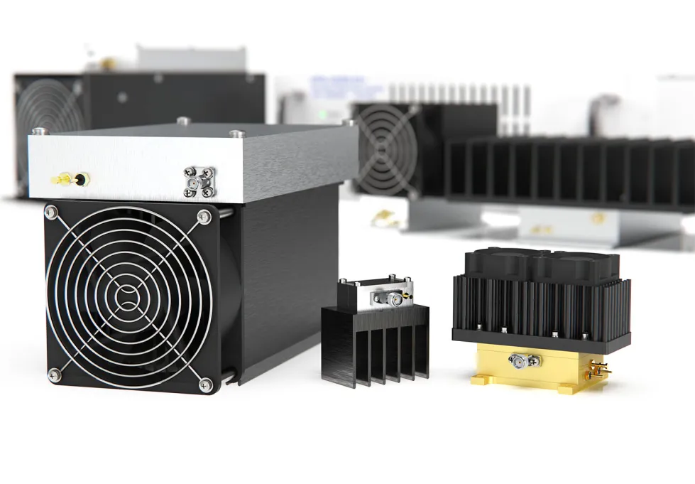
Mini-Circuits has a longstanding legacy of fully specifying the thermal performance of our amplifiers, with or without a Mini-Circuits-supplied heatsink. Recently, it has become so commonplace for custom heatsinks to be utilized with Mini-Circuits power amplifiers that the power amplifier thermal characteristics are now expressed differently. Although the thermal resistance of the Mini-Circuits-supplied heatsink is no longer explicitly provided for newer models this is easily calculated from the specifications given for any model power amplifier. Basic calculations are all that is needed to arrive at any parameter of interest when analyzing thermal characteristics of any Mini-Circuits power amplifier.
Wideband Connectorized Amplifiers Support Over-The-Air (OTA) Transmitter & Receiver Testing for 5G FR2 Bands

The advent of 5G networks has already begun ushering in a whole new generation of wireless devices and applications, and device manufacturers are racing to be the first to market. In order to meet the 5G standard for commercial wireless communication, device manufacturers need to develop powerful transmitters and receivers that operate in the millimeter wave range. This comes with a number of challenges, one of which is testing and qualification. Due to the wireless nature of these devices, manufacturers need to conduct testing in real-world conditions, which isn’t possible using the conventional approach of connecting devices under test (DUTs) to instruments with coaxial cables. Over-the-air (OTA) testing allows engineers to more realistically simulate real-world device performance in the lab environment.


