Understanding RF/Microwave Push-Pull Amplifier Design
Remarkably, the concept of the push-pull connection spans three centuries. William W. Dean of the Bell Telephone Company of Missouri first described the push-pull-connected telephone transmitter in Patent No. 549,477, dated November 5, 1895.1 Next, Sir John Ambrose Fleming invented the first vacuum tube in 19042 and while Lee De Forest added the grid to Fleming’s “valve” in 1906, calling it the “audion,” it was Fritz Lowenstein in his April 24, 1912 patent application who first discovered that applying a negative bias to the grid of De Forest’s tube turned it into an audio amplifier.
Edwin Henry Colpitts of the Western Electric Company was awarded Patent No. 1,128,292, for an “electric wave amplifier” on February 16, 1915, which covered the push-pull circuit by connecting two vacuum tubes like De Forest’s audions like a primitive precursor to the transistor.3,4 Over a hundred years ago, Colpitts recognized that “a certain amount of distortion in the output waves is avoided”3 by utilizing this configuration.
Fast-forward over 100 years and transpose kHz with GHz; we find the push-pull amplifier configuration everywhere. This article describes a simple, modern-day, push-pull amplifier configuration along with its performance advantages. Several practical construction methodologies for the main components are reviewed, and an example of a high-power, broadband application is presented. Finally, applications of the push-pull amplifier configuration are discussed.
Basic Push-Pull Amplifier Configuration
More than a century after the invention of the push-pull amplifier, a myriad of different configurations has been developed, some of which require prerequisite knowledge of the operation of complex transformers. The focus of this application note is on the push-pull amplifier itself. An example showing a pair of generic devices combined with simple transformer baluns is shown in Figure 1.
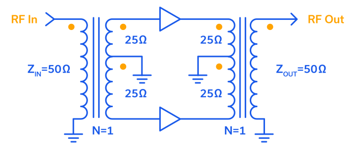
A balun transformer (short for balanced-to-unbalanced) is utilized to connect an unbalanced (single-ended, ground-referenced) signal to a balanced (differential, ±180⁰) pair of signals, or vice versa, to combine a differential pair into a single-ended signal. The baluns shown in Figure 1 are also transformers (hence the term “balun transformer”) which provide isolation in addition to impedance transformation. In this example, we have chosen to illustrate perhaps the simplest of impedance transformations by setting the turns ratio nOUT/nIN = N = 1. Note that by nOUT we mean all the turns on the center-tapped winding. Therefore, as shown in Figure 1, the impedance of each half of the center-tapped winding is equal to ZHALF = (N2)(ZIN)/2 = (N2)(ZOUT)/2 = (1)(50Ω) = 25Ω. A turn ratio that differs from unity would also change the primary-to-secondary impedance ratio.
Push-Pull Amplifier Operation
The balun transformer with a center-tapped secondary in Figure 1 is a fundamental element of the push-pull amplifier configuration, and the dot convention is shown to make the figure comprehensive. (Recall that the dot convention specifies that the polarity is the same at all terminals marked with a dot). Since the amplifiers themselves are generic, they can be assumed to be ideal, perfectly matched in gain and phase, and noninverting. The push-pull amplifier works by taking the unbalanced (single-ended) primary signal, splitting it into a balanced pair of two signals that are 180⁰ out-of-phase, then driving two amplifying devices, one at an effective phase shift of 0⁰ and the other at -180⁰.
The input balun transformer is then mirrored at the output of the amplifier pair such that the balanced or center-tapped winding may be considered the primary, and the single-ended winding the secondary. The amplifier output signals are applied to the center-tapped primary, and since the devices are perfectly out-of-phase when one amplifier is driving current, the opposing amplifier is sinking current. Stated differently, when one amplifier operates at maximum voltage, the other amplifier will operate at minimum voltage, per the dot convention. This pushing and pulling action across the center-tapped secondary (hence the name, “push-pull amplifier”) results in the devices combining to yield the sum of their powers, or twice the power of each amplifier at the single-ended winding of the output balun transformer. Typically, the device with the highest output voltage (appearing to source current) can be viewed as “pushing” and the one with the lowest output voltage (appearing to sink current) as “pulling.”
In addition to the inherent power combination that occurs in the push-pull amplifier, one of its primary advantages is the cancellation of even-order harmonics. Just as the fundamental input signal is split into two signals 180⁰ out-of-phase, the second harmonic, or 2f0 is split into two signals that are 360⁰ out-of-phase, which is equivalent to in-phase. Imagine the center-tapped primary of the output balun transformer being excited by two signals of identical phase at a frequency of 2f0. In an ideal case, there would be no current flow in the winding, no transformer flux, and no second harmonic output. Essentially, any even-order harmonic signal will result in purely common mode excitation of the balun transformer.
Receiver LNAs and broadband power amplifiers that span greater than an octave of bandwidth benefit from this harmonic cancellation. That’s why this fundamental and longstanding amplifier configuration is so ubiquitous, having found its way into everything from low-power LNAs to ultra-high-power transmitters.
Balun Transformer Variants in Push-Pull Amplifier Designs
While the example in Figure 1 shows a generic push-pull amplifier configuration, real-world application circuits vary widely. The input and output baluns in particular offer the designer many options depending on the requirements and desired performance parameters for a given system. In the 127 years since Dean first described the push-pull configuration, and the 107 years since Colpitts invented the push-pull amplifier, volumes have been written about how to match pairs of amplifier devices and how to construct the various combining mechanisms. The full breadth of design techniques and topologies goes beyond the scope of this article, but let’s discuss a few examples by way of introduction.
One of the most compelling developments in RF component design of the 20th century was the invention of the Guanella balun (see Figure 2).5 Gustav Guanella, a Swiss Radio Engineer, discovered that a balun transformer could be constructed from coaxial transmission line. Another article on the Mini-Circuits blog discussing RF transformer types explains, “This 1:1 type of balun transformer creates a high choking reactance on the outer conductor of the coaxial cable, effectively reducing common mode signals while allowing the internal currents of the coaxial transmission line to pass unimpeded.”7 Guanella filed for his patent on April 5, 1945, and many physical balun transformers designed today make use of this early work.
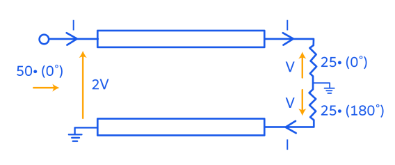
Notice how the Guanella balun shown in Figure 2 closely resembles the generalized balun transformers of Figure 1. This topology is inherently shielded and can achieve over a decade of bandwidth, making it ideal for wideband push-pull amplifier designs that might otherwise be constrained by the frequency range of the baluns used.
Just as push-pull amplifiers in the VHF/UHF frequency range long ago achieved well over a decade of bandwidth, the frequency, bandwidth and power level of push-pull amplifiers will continue to increase with advances in planar balun technologies, such as the Marchand balun. GaN semiconductor technology has already been combined with Marchand baluns to achieve octave-bandwidth push-pull amplifiers in S-band (0.5 GHz to 2.2 GHz)9 and X-band (6 to 12 GHz)10 operating frequencies. A pair of distributed GaAs amplifiers has even been combined using Marchand baluns to achieve a bandwidth of 4-20 GHz.11
Again, these are only a few examples of how different baluns can be used to achieve desired performance in push-pull amplifier designs. Readers are encouraged to learn more about the various types of baluns here on our blog and to explore the wide selection of baluns in stock on our website.
IP2 & IP3 Performance of Dual-Matched MMIC Amplifiers in Push-Pull Configuration
Practical implementation of push-pull amplifier designs requires a matched amplifier pair with as little variation in gain and phase as possible. While this can be achieved using two discrete gain stage elements, fabricating both amplifier circuits on a single MMIC is perhaps the most effective way of minimizing performance variation while significantly reducing physical board real estate. Mini-Circuits offers a broad selection of dual-matched amplifiers optimized for push-pull operation over a wide bandwidth. As a convenience to designers using these devices in push-pull, many models include test board schematics and data for push-pull operation, replete with IP2 measurements.
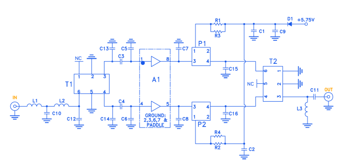
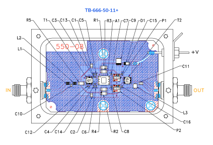
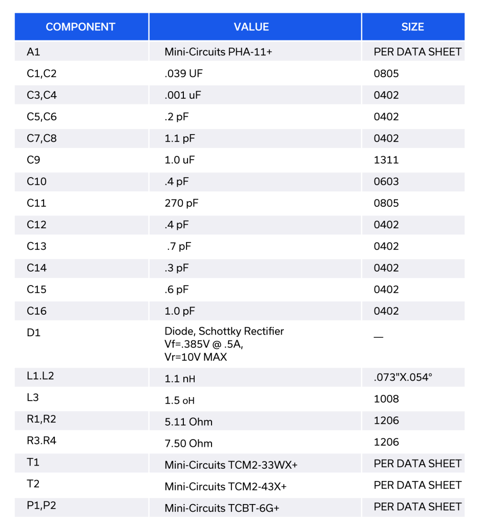
PHA-11+ is among Mini-Circuits’ most popular dual-matched MMIC amplifier designs and has become a staple component for many designers in the industry. Mini-Circuits has characterized this model in three different push-pull configurations. Evaluation boards for each of these circuits are available for testing at the customer’s end as well. The schematic and eval board for one of these characterization circuits is shown in Figure 3.
References
- William W. Dean, Local Transmitter Circuit for Telephones, US549477A – Of same place – Google Patents
- John Ambrose Fleming – Wikipedia
- Edwin Henry Colpitts, Electric Wave Amplifier, US1128292A – Electric-wave amplifier. – Google Patents
- WESTERN ELECTRIC CO., Inc., et al., v. WALLERSTEIN. Circuit Court of Appeals, Second Circuit. July 18, 1932. WESTERN ELECTRIC CO. v. W | 60 F.2d 723 (1932) | 0f2d7231537 | Leagle.com
- Push-Pull circuits and Wideband Transformers, SEMELAB PLC, Push-Pull Transistors (rf-design.co.za)
- G. Guanella; “Novel Matching Systems for High Frequencies”; Brown-Boveri Review Sept 1944
- Demystifying Transformers: Baluns and Ununs – Mini-Circuits Blog (minicircuits.com), Urvashi Sengal and William Yu, July 9, 2020
- NXP Document Number: MRFE6VP100H Rev. 0, 5/2012, MRFE6VP100HR5, MRFE6VP100HSR5 1.8-2000 MHz, 100 W, 50 V Broadband RF Power LDMOS Transistors (nxp.com)
- A broadband envelope-tracking push-pull GaN power amplifier using grounded-coplanar ring Marchand balun | IEEE Conference Publication | IEEE Xplore
- A 6-12 GHz Push-Pull GaN Amplifier for Low Harmonic Drive Applications (researchgate.net)
- A 4–20 GHz, multi‐watt level, fully integrated push–pull distributed power amplifier with wideband even‐order harmonic suppression – Nguyen – 2019 – IET Microwaves, Antennas & Propagation – Wiley Online Library
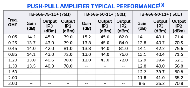
Gain, OIP3 and OIP2 specs from the datasheet are shown in Figure 4. Note that TB-666-50-11+ is optimized for the best combination of bandwidth, IP3 and IP2 performance. TB-566-50-11+ maximizes IP3 and IP2 performance over a slightly reduced bandwidth, while TB-566-75-11+ is matched for 75Ω characteristic impedance. This data illustrates not only the superior linearity and even-order harmonic cancellation of the device in push-pull amplifier configuration but also its flexibility as a building block for a variety of different system requirements.
The Enduring Nature of the Push-Pull Amplifier
For more than a century, push-pull amplifiers have found their way into many types of systems including communications, radar and electronic countermeasures (jamming). Inherent power combination and even order harmonic cancellation are beneficial for both the receive and transmit sides of these broadband systems. In review, we have presented a simple push-pull configuration and a basic explanation of its operation. The role of different balun types in real-world implementations was discussed, and a push-pull application circuit for Mini-Circuits’ PHA-11+ dual-matched MMIC amplifier was provided with test data by way of example.
Push-pull amplifiers will long remain an essential choice in modern RF/microwave systems. In concert with the never-ending quest for more bandwidth and more power with less distortion, the push-pull amplifier is one configuration that is certain to be developed with every advancing technology.
Mini-Circuits’ industry-leading selection of RF balun transformers comprises core and wire, LTCC and MMIC technologies in a variety of impedances and bandwidths. These parts are used widely in push-pull amplifier designs as well as other applications. Contact [email protected] to discuss your project needs with our engineers.


