MMIC Package Customization – Footprint-Compatible Solutions for Your System
MMIC Package Customization – Footprint-Compatible Solutions for Your System Obsolescence Management and EOL Part Replacement LTB (Last Time Buy) and EOL (End of Life) are among the most unwelcome acronyms in the ranks of Procurement and Engineering. Component obsolescence saddles customers with the burden of tying cash up in inventory on their balance sheet, or […]
MMIC Amplifiers with Shutdown and Bypass Features De-Mystified

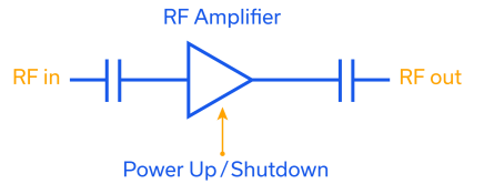
Mini-Circuits’ TSS- and TSY-families of MMIC amplifiers feature a versatile combination of performance characteristics including high dynamic range and very low noise figure with wideband frequency coverage from VHF up to mmWave applications. These product families also include additional features of shutdown and bypass functionality. These features often lead to customer questions about the difference between bypass and shutdown, which products have which features, and the benefits of each. This article will explain how these features work, and provide an overview of some of the applications are where shutdown and bypass functions are most commonly used.
MMIC Technologies: Pseudomorphic High Electron Mobility Transistor (pHEMT)

Pseudomorphic High-Electron-Mobility-Transistor (pHEMT) is one technology Monolithic Microwave Integrated Circuit (MMIC) designers and fabs use to develop and manufacture microwave integrated circuits. pHEMT has gained popularity as a building block of many MMICs produced by electronics manufacturers like Mini-Circuits due to its superior wideband performance characteristics including low noise figure, high OIP3 and excellent reliability up to 40 GHz and beyond. pHEMT uses heterojunctions between semiconductors of different compositions and bandgaps to achieve outstanding high-frequency performance. This article delves into the physics of pHEMT operation, advantage, and reliability test results. A link to a summary of Mini-Circuits’ pHEMT products is also provided.
A Primer on RF Semiconductors (MMICs)
A Primer on RF Semiconductors (MMICs) Radhakrishna Setty, Technical Advisor Introduction Semiconductors are ubiquitous in modern society. In addition to microprocessors for computing technologies, they are used in practically every active wireless communications system including cell phone towers, cell phones, radars and satellites to name a few. Mini-Circuits designs and produces several semiconductor-based (MMIC) components […]
Combining MMIC Reflectionless Filters to Create Ultra-Wideband (UWB) Bandpass Filters

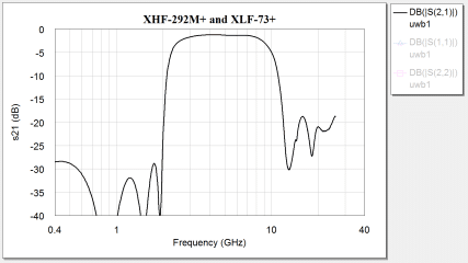
Ultra-Wideband (UWB) radio is defined as any RF technology utilizing a bandwidth of greater than ¼ the center frequency or a bandwidth greater than 500 MHz [1] [2]. While UWB has been a known technology since the end of the nineteenth century, restrictions on transmission to prevent interference with narrow-band, continuous wave signals have limited its applications to defense and relatively few specially licensed operators [1]. In 2002, the FCC opened the 3.1 to 10.6 GHz band for commercial applications of Ultra-Wideband technology, and since then UWB has become a focus of academic study and industry research for a promising variety of emerging applications. To prevent interference with neighboring spectrum allocations like GPS at 1.6 GHz, the FCC has imposed specific rules for indoor and outdoor transmission of UWB signals, limiting transmissions in the permitted frequency range to power levels of -41 dBm/MHz or less.
MMIC Die Testing Made Easy with Ultra-Wideband 0 dB Attenuator (Thru-Line) Dice

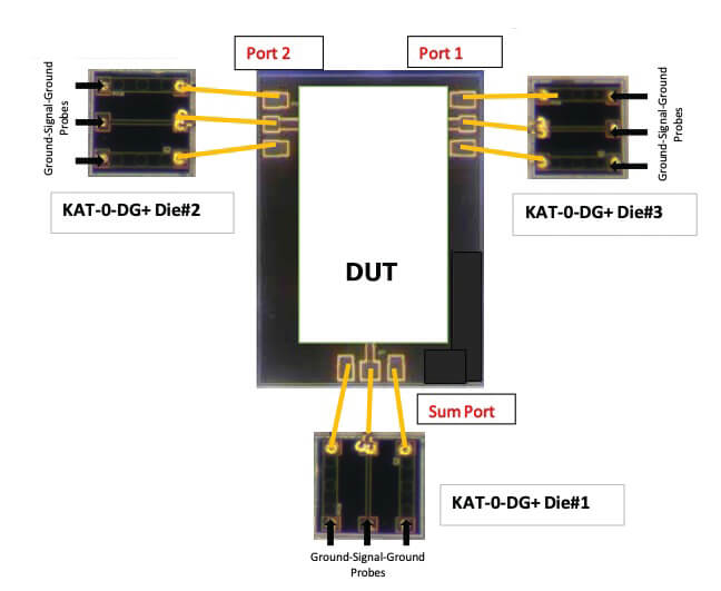
Microwave hybrid circuitry is generally built by integrating several discrete dice via wire bonding. Circuit designers are faced with the task of predicting the performance of hybrids, which comes with some specific challenges.
Flattening Negative Gain Slope with MMIC Fixed Equalizers

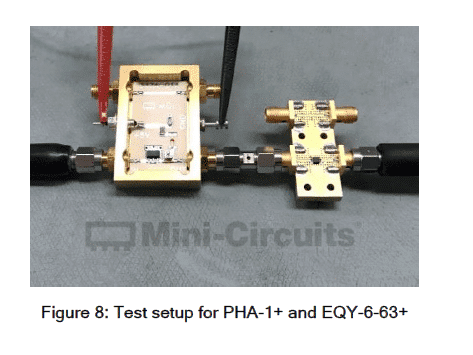
Equalizers are devices used to compensate for negative gain slope in the frequency response of a wide variety of RF systems. Unlike a standard attenuator with a flat frequency response, an equalizer is a unique kind of attenuator which exhibits lower insertion loss as frequency increases with some known slope. This is a useful characteristic for system designers working in wideband applications where the gain response of circuit elements or of the entire RF chain often varies across frequency.
MMIC Amplifiers Stretch the Boundaries of Dynamic Range in VHF/UHF Communications

The noise figure and linearity of low noise amplifiers are critical factors in maximizing sensitivity and dynamic range in RF receiver design. The amplifier noise figure determines the weakest signal the amplifier can discern, and the IP3 determines the degree to which intermodulation products from nearby signals interfere with the desired signal. The lower the noise figure and the higher the IP3 of the amplifier at the receiver input, the greater the sensitivity and Spurious Free Dynamic Range (SFDR) of the receiver.


