Combining MMIC Reflectionless Filters to Create Ultra-Wideband (UWB) Bandpass Filters
Brandon Kaplan, Mini-Circuits Publications
Matt Morgan and Tod Boyd, National Radio Astronomy Observatory
UWB: Background and Emerging Applications
Ultra-Wideband (UWB) radio is defined as any RF technology utilizing a bandwidth of greater than ¼ the center frequency or a bandwidth greater than 500 MHz [1] [2]. While UWB has been a known technology since the end of the nineteenth century, restrictions on transmission to prevent interference with narrow-band, continuous wave signals have limited its applications to defense and relatively few specially licensed operators [1]. In 2002, the FCC opened the 3.1 to 10.6 GHz band for commercial applications of Ultra-Wideband technology, and since then UWB has become a focus of academic study and industry research for a promising variety of emerging applications. To prevent interference with neighboring spectrum allocations like GPS at 1.6 GHz, the FCC has imposed specific rules for indoor and outdoor transmission of UWB signals, limiting transmissions in the permitted frequency range to power levels of -41 dBm/MHz or less.
Research to date has explored many potentially valuable applications for UWB technology. For example, the wide bandwidth of UWB provides high channel capacity, allowing very high-speed data transfer at very low power. While the FCC power mask limits the range of UWB transmission to within roughly 10 meters, its high-speed, low-power characteristics have made UWB an attractive technology for certain short-range M2M communication applications like Wireless Personal Area Networking (WPAN) as well as low power sensor networks.[1] UWB has also proven viable as a technology for new applications in detection, positioning and imaging. Modulation of UWB signals using ultra-short pulses in the order of nanoseconds enables precise location and ranging at the centimeter level [1] [6]. This capability has useful potential for military surveillance systems and other high-accuracy location and detection applications. The same high-resolution, high-penetration properties have also attracted research in the medical field, and a number of medical imaging applications have shown successful results. UWB systems have been used for non-invasive, precise detection of heart movements, and high-fidelity imaging using safe, non-ionizing radiation as an alternative to more harmful X-ray imaging.[3]
Suitability of Reflectionless Filters for UWB RF Front End
While UWB technology has shown much potential, many design challenges remain in bringing the technology to a stage of wider industry adoption and commercialization. One of those challenges has been developing RF filters with a wide enough passband, flat response over the whole band, and sufficient selectivity to meet FCC specifications. Several approaches have been studied to achieve the desired response utilizing microstrip technology [2] [4] [5]. While these approaches have achieved varying degrees of success, they each come with drawbacks. Microstrip UWB filter designs typically occupy greater than a square inch of board space and tend to be costlier than practical for volume production.
Mini-Circuits’ reflectionless filters present an attractive alternative to existing approaches for UWB filters. Because reflectionless filters absorb and terminate stopband signals rather than reflecting them back to the source, they give designers the ability to cascade filters in multiple sections without generating standing waves due to impedance mismatch between stages and other undesirable effects. This characteristic allows combination of low pass and high pass filters to create a bandpass response, a technique that becomes useful for the purpose of designing UWB filters.
In addition to their intrinsic cascadability, reflectionless filters are uniquely suited for UWB filter designs for at least three reasons:
- Reflectionless high pass filters have broad enough passbands to achieve the desired bandwidths for UWB; most other filter technologies do not.
- The low pass filters offer cut-offs that extend high enough in frequency to achieve 3 dB bandwidths well above 100%.
- The good impedance match at the band edges allows multiple filters to be cascaded in series without causing distortion of the passband shape, whereas cascading conventional filters can often create standing waves between stages and introduce passband ripple and phase instability.
Moreover, while competing approaches employ transmission lines, reflectionless filter topologies are based on lumped elements and produced using MMIC technology resulting in much smaller size, lower cost, and excellent repeatability, making them suitable candidates for volume production. Models are available in package sizes as small as 2x2mm and in bare die format for chip and wire integration.
With these advantages in mind, the case studies below explore possibilities for use of reflectionless filters in UWB filter design. Five cases are presented using standard reflectionless filter models available off the shelf from Mini-Circuits. Simulation results and measured data are presented to illustrate the various advantages of reflectionless filters in UWB applications. Finally, a design is presented that meets UWB bandwidth requirements and conforms to the specifications of the FCC spectral mask.
Case 1: General Proof of Concept
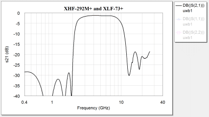
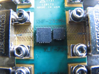
To illustrate the technique, two reflectionless filters were combined to create a bandpass response. In this case, high pass model XHF-292M+ and low pass model XLF-73+ were used. The preliminary simulation shown in Figure 1 exhibits a 3 dB passband from 2.3 to 9.7 GHz (4.2:1 or 123% bandwidth).
To validate these results, the filters were mounted on a test board as shown in Figure 2. Insertion loss was swept from 0.1 to 40 GHz and again from 45 MHz to 2 GHz, the later with fine resolution to capture the low frequency details. The measurement was then corrected for the fixture by subtracting the measured loss of a straight thru-line.
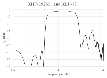
The measured data for this filter is plotted in Figure 3. The response confirms the simulation results, exhibiting a 3 dB bandwidth of roughly 2.4 to 9.7 GHz (121% or 4:1). As expected, cascading the units shows no effect on the flatness of the passband. The higher rejection on the low end is due to the two-section design of the high-pass filter used in this case.
Case 2: Maximizing Bandwidth
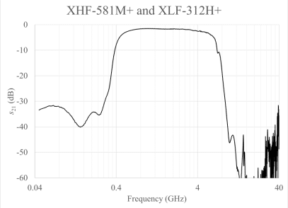
Case 1 establishes the viability of the technique by combining high pass and low pass reflectionless filters to create an ultra-wideband bandpass response. By employing the same technique, we can now experiment with different models to shape the response and achieve desirable characteristics. In this case, we seek to create the widest passband possible with the models available, combining two-section, high pass model XHF-581M+ and low pass, three-section model XLF-312H+. In addition to the wide bandwidth, because this filter incorporates two and three section designs, we also expect to see very high rejection in the upper and lower stopbands.
A simulation combining these two models in series is shown in figure 4, exhibiting a 3 dB passband from 450 MHz to 5.7 GHz (12.7:1 or 171% bandwidth). Note that a logarithmic frequency scale is used to better show the shape of the response. Also note the lower stopband rejection greater than 30 dB and upper stopband rejection reaching the 50 to 60 dB range, again a function of the two- and three-section designs used in this case.
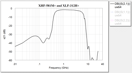
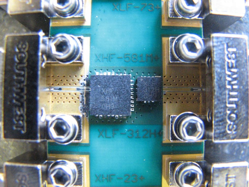
The filters were mounted on the test board shown in Figure 5, and again insertion loss was swept from 0.1 to 40 GHz and from 450 MHz to 2 GHz at fine resolution to capture more detail at low frequency. The measurements were corrected for the fixture by subtracting the loss of a straight thru-line. The measurement plot is shown in Figure 6. Again, note the logarithmic frequency scale to better represent the filter behavior. The filter achieves a 3 dB bandwidth from roughly 500 MHz to 5.2 GHz (10:1 or 165% bandwidth). The measured data exhibits a slightly narrower passband than the simulation, but still achieves greater than a full decade of bandwidth. As expected lower stopband rejection is between 30 and 40 dB, and upper stopband rejection ranges from 40 to greater than 60 dB. The passband shows excellent flatness with no distortion from adverse interactions between the filter stages.
Case 3: Confirming Stopband Rejection up to 40 GHz without Re-Entry
It’s clear from Cases 1 and 2 that combining reflectionless filters can achieve ultra-wide passbands, allowing bandwidth at least up to a full decade, amply supporting the bandwidth requirements of UWB applications. Another concern for system designers building UWB transmitters is the potential for “re-entry” out of band at higher frequencies. Such unintentional radiation can potentially interfere with signals at neighboring frequencies and violate the FCC rules. Therefore, UWB filters must exhibit good stopband rejection without re-entry up to a very high frequency.
Reflectionless filters offer advantages in this regard. In part due to their fabrication using MMIC technology, reflectionless low-pass filters provide stopband rejection extending up to 40 GHz. Many conventional filter approaches would suffer re-entry over this bandwidth. This characteristic allows us to create a UWB filter response that meets the FCC power mask up to 40 GHz without re-entry.
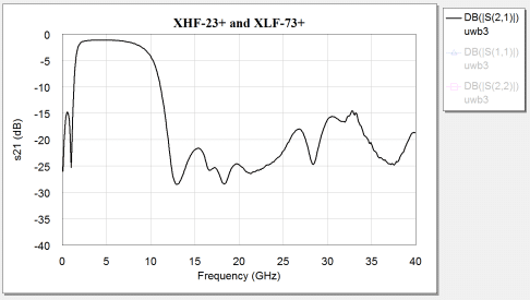
In this case, we combine high pass model XHF-23+ and XLF-73+, both single section designs. S-parameter simulation for these models is shown in figure 7, exhibiting a 3 dB passband from 1.6 GHz to 10 GHz (6.25:1 or 145% bandwidth). Stopband rejection remains better than 15 dB up to 40 GHz without re-entry.
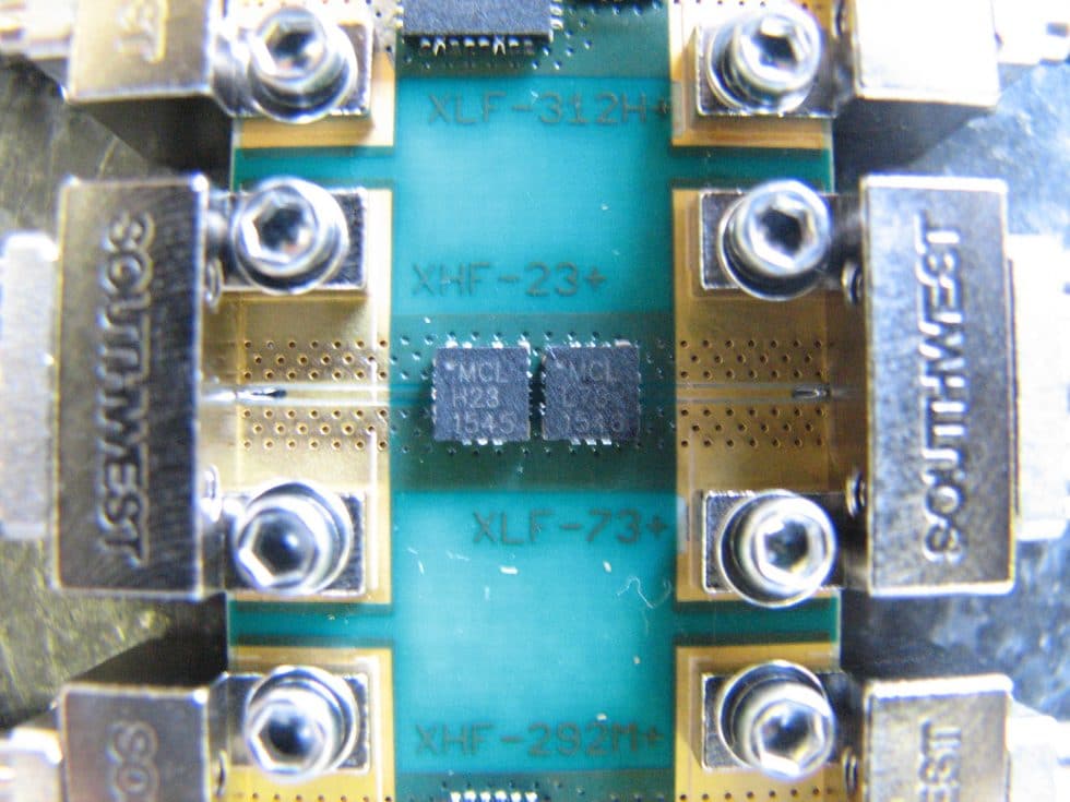
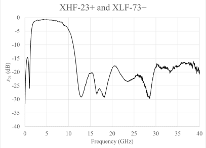
Figure 9 shows measured insertion loss for the two filters on the test board shown in figure 8. The same measurement method was used as in the previous cases. The measured response shows a 3 dB passband from roughly 1.7 to 9.3 GHz (5.5:1 or 138% bandwidth), with stopband rejection well above 15 dB up to 40 GHz. This result confirms that this technique can be used in UWB applications without unintentional emissions out of band due to re-entry.
Case 4: Combining Reflectionless Filters and LTCC Filters to Sharpen Selectivity
We’ve shown that reflectionless filters can be combined to achieve ultra-wide passbands and that this approach provides excellent stopband rejection up to 40 GHz without re-entry. To come closer to the real-world requirements of a UWB system under FCC specifications, it may be necessary to sharpen the transition to conform to the FCC spectral mask.
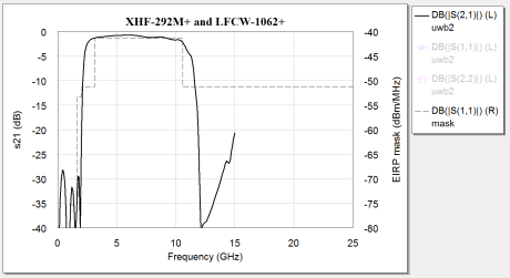
The absorptive characteristic of reflectionless filters means that they’re not only cascadable with other reflectionless filters, but also with all manner of conventional filters. This hybrid approach allows us to achieve the desired wideband response while incorporating the selectivity of another filter technology. In this case, we combine a two-section, high pass reflectionless filter (XHF-292M+) with a low pass LTCC filter (LFCW-1062+) to take advantage of the greater selectivity of the latter. Simulation results of this combination are shown in figure 10 along with the FCC spectral mask for indoor UWB transmissions (dotted line and right axis). This combination exhibits a passband from 2.4 to 10.9 GHz (4.5:1 or 128% bandwidth). The deep rejection at the lower stopband below 2.4 GHz keeps transmissions at neighboring frequencies like GPS at 1.6 GHz clean of emissions. Note that while the data for the LTCC filter stops at 15 GHz, it’s clearly approaching some re-entry at that point. This is a trade-off of incorporating a different filter technology.
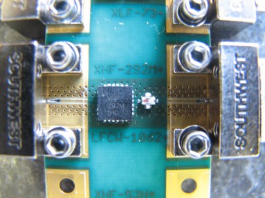
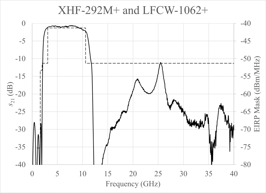
The test board for this filter combination is shown in Figure 11, and the measured data for insertion loss shown in Figure 12. This filter has a measured 3 dB passband from roughly 2.45 to 10.9 GHz (4.5:1 or 127% bandwidth), very consistent with the simulation. Combination with the LTCC filter introduces a few noteworthy differences from the previous cases. First, the insertion loss suffers some re-entry around 25 GHz, enough to just cross the FCC limit. Also, the return loss in the upper stopband (not shown) obviously degrades because the LTCC filter is fully reflective in its stopband.
Overall, the filter approaches the desired response for real-world UWB transmission, but is still a little wider than ideal. A similar approach with the right combination of filters may come closer to the ideal filter behavior.
Case 5: UWB Filter Meeting the FCC Emission Mask for Indoor UWB Transmission
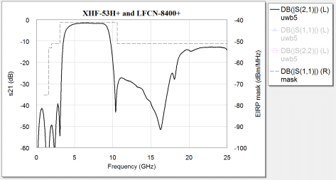
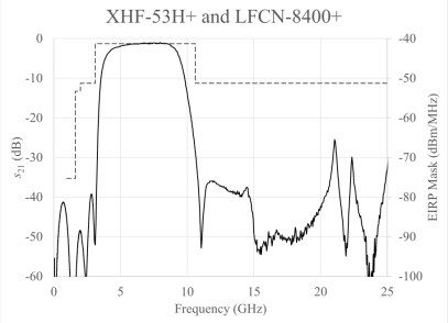
To realize filter response closer to the ideal for real-world UWB transmission, careful model selection led to a combination of three-section, high pass reflectionless filter, XHF-53H+ and low-pass LTCC filter LFCN-8400+. A simulation of these filters is shown in Figure 13 with the FCC mask for indoor UWB transmission (dotted line and right axis). The simulated 3 dB passband is from 3.9 to 9.4 GHz (2.4:1 or 83% bandwidth). Although the LTCC filter does show some re-entry in the upper stopband, it isn’t significant enough as to become a secondary passband and remains well below the FCC mask.
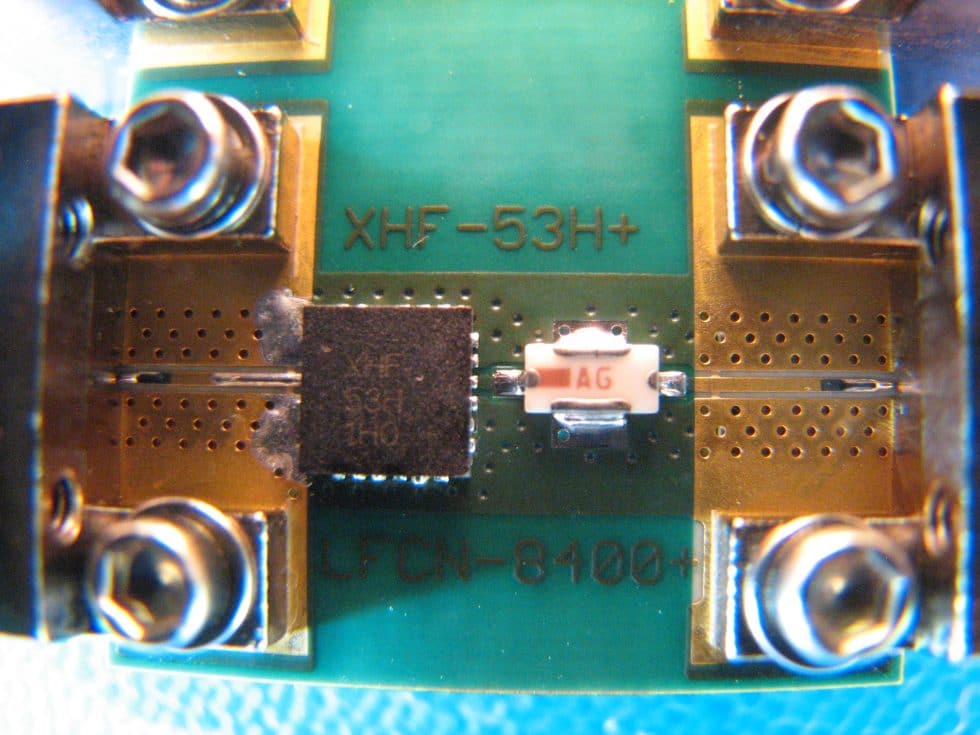
The test board for this filter combination is shown in Figure 14, and the measured data for insertion loss is shown in Figure 15. The filter response exhibits a 3 dB passband from 4.25 to 9.15 GHz (2.2:1 or 73%), and conforms nicely to the FCC spectral mask. Again, the reflectionless-LTCC hybrid approach comes with some tradeoffs that warrant mention. First, as expected the filter exhibits reflective behavior in the upper stopband, and return loss degrades above 9 GHz. Secondly, while the upper stopband achieves excellent rejection up to 25 GHz, it suffers some unexpected re-entry around the 30 to 35 GHz region, and a different low pass filter model may be needed to suppress this re-entry at higher frequencies. Nonetheless, this example illustrates how reflectionless filters can be successfully cascaded with other filter designs to achieve the desired passband shape for UWB communications.
Conclusion
The experiments in this article show how reflectionless filters provide a novel and highly viable approach to filter design in UWB applications. The examples shown all employ standard, catalog models available off the shelf from Mini-Circuits. Mini-Circuits currently offers over 50 reflectionless filter models from stock, and custom designs are available on request to refine performance to meet exact application requirements.
The approach demonstrated here provides designers several practical advantages over previously studied approaches. In addition to electrical properties that make reflectionless filters ideal for the requirements of UWB applications, the filters are smaller, less costly, and more repeatable relative to competing technologies, making them suitable candidates for use in commercial applications where volume manufacturability may be a requirement. While this article highlights the specific suitability of reflectionless filters for UWB applications, it should also broaden the reader’s appreciation for the flexibility of these innovative products as building blocks with many valuable advantages in RF system design, many of which still remain to be explored.
Developing a new design for UWB? Talk to one of our engineers about how reflectionless filters can improve performance in your system.
References
[1] J. Wilson, Intel Corporation, “Ultra-Wideband: A Disruptive RF Technology?” Version 1.3, 2002
[2] C. Hsu, F. Hsu, and J. Kuo, “Microstrip Bandpass Filters for Ultra-Wideband (UWB) Wireless Communications,” 2005 IEEE MTT-S International Microwave Symposium Digest, Oct. 2005
[3] J. Pan, “Medical Applications of Ultra-Wideband (UWB),” Washington University St. Louis, Apr. 2008, retrieved from http://www.cse.wustl.edu/~jain/cse574-08/ftp/uwb/index.html
[4] L. Zhu, S. Sun and W. Menzel, “Ultra-Wideband (UWB) Bandpass Filters Using Multiple-Mode Resonator,” IEEE Microwave and Wireless Components Letters, Vol. 15, No. 11, pp. 796 – 798, Nov. 2005
[5] A. Sheta and I. Elshafley, “Microstrip Ultra-Wide-Band Filter,” PIERS Proceedings, Marrakesh Morocco, pp. 198 – 200, March 20-23, 2011
[6] C. Cansever, “Design of a Microstrip Bandpass Filter for 3.1 to 10.6 GHz UWB systems,” Syracuse University, 2013


