MMIC Technologies: Pseudomorphic High Electron Mobility Transistor (pHEMT)

Pseudomorphic High-Electron-Mobility-Transistor (pHEMT) is one technology Monolithic Microwave Integrated Circuit (MMIC) designers and fabs use to develop and manufacture microwave integrated circuits. pHEMT has gained popularity as a building block of many MMICs produced by electronics manufacturers like Mini-Circuits due to its superior wideband performance characteristics including low noise figure, high OIP3 and excellent reliability up to 40 GHz and beyond. pHEMT uses heterojunctions between semiconductors of different compositions and bandgaps to achieve outstanding high-frequency performance. This article delves into the physics of pHEMT operation, advantage, and reliability test results. A link to a summary of Mini-Circuits’ pHEMT products is also provided.
Positive Gain Slope Amplifiers Compensate for Gain Roll-Off in Wideband Systems
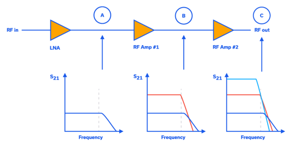
Meeting gain roll-off and gain flatness requirements over frequency is a common problem in many modern-day discrete RF transceivers. Ideally, the gain in the signal path of an RF transceiver should be flat over frequency in the band of interest. However, each component in the RF line-up has a finite bandwidth, which can cause the overall system gain response to roll-off over frequency. This is seen as negative slope in a graph of gain versus frequency. This behavior makes meeting gain flatness specifications for these transceivers very challenging to achieve, particularly over wide bandwidths.
Mesh Network Simulators for Wireless Device Testing
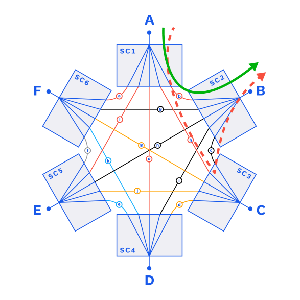
A mesh network is a wireless network architecture in which three or more devices, also called nodes, are all connected to each other. Every node in the mesh network is able to communicate with some or all of the other nodes in the network. This type of architecture is distinct from traditional “hub and spoke” networks in which all devices connect to a central hub through which they communicate with other devices. In the real world, nodes can be wireless routers, cellular handsets, personal computers or any other device capable of sending and receiving signals. Home Wi-Fi networks, local area networking, military and public safety communications are all examples of applications where mesh networks are commonly employed.
LTCC Meets 5G: Advanced Filter Designs Achieve True mmWave Performance

Low Temperature Co-fired Ceramic (LTCC) substrate technology is one major area of Mini-Circuits’ R&D investment. As a result of its long-term investments in materials, manufacturing processes, simulation and testing capability, research on novel circuit topologies, and world-class engineering talent, the company has developed a new series of filters based on LTCC technology that support the millimeter wave (mmWave) 5G market with a small footprint, low cost, and superior performance to competitive products and technologies. This includes the newly developed bandpass filters specifically designed for the 5G FR2 n257, n258, n260 and n261 bandwidths, low pass filters supporting bandwidths from DC up to 30 GHz and beyond, and high pass filters with passband cut-offs up to 36 GHz at the time of this writing.
Mini-Circuits Test Equipment Adapts to Your Changing Needs
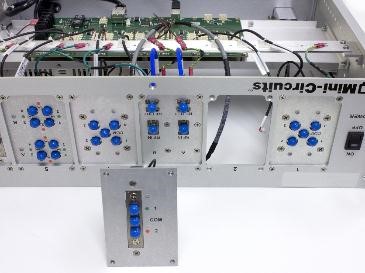
Mini-Circuits ZTM-series modular test system adapts to your changing needs. The system is designed with complete flexibility to replace old hardware and swap out one component for another without returning equipment to the factory for service. The company’s hand-flex cables can be used to connect hundreds of possible routing configurations.
Best Practices for Additive Phase Noise Measurements in Amplifiers

This article will review the challenges in measuring additive phase noise in Amplifiers and present details of the measurement setup Mini-Circuits uses to perform these measurements accurately and reliably. We will also dive into the specifics of additive phase noise readings and explain how to interpret phase noise values and measurement plots.
A Primer on RF Semiconductors (MMICs)
A Primer on RF Semiconductors (MMICs) Radhakrishna Setty, Technical Advisor Introduction Semiconductors are ubiquitous in modern society. In addition to microprocessors for computing technologies, they are used in practically every active wireless communications system including cell phone towers, cell phones, radars and satellites to name a few. Mini-Circuits designs and produces several semiconductor-based (MMIC) components […]
LTCC Filters Enhance Differential Circuit Designs
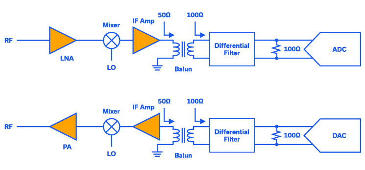
Today’s analog-to-digital converters (ADC) and digital-to-analog converters (DAC) are typically differential circuit designs. Differential circuits provide many advantages over single-ended designs, including common-mode rejection of thermal noise, even order harmonics, and power supply noise and spurs. Additionally, differential circuits allow for half the voltage swing on each output compared to a single-ended design. Discrete transceivers on the other hand are often designed with single-ended, 50Ω matched components such as low noise amplifiers (LNAs), mixers and IF gain amplifiers. To interface with a differential ADCs or DACs, a single-ended-to-differential, or differential-to-single-ended, a transformer or balun is needed.
Peak and RMS RF Power Detectors for High-Frequency Signal Measurement

Power detectors are widely used RF components that convert an RF input signal into an output DC voltage proportional to the RF input power. Power detectors are useful for a number of applications that include automatic gain control circuits, transmit antenna power monitoring, protecting sensitive circuits from pulses and power spikes as well as a wide range of test and measurement applications. Mini-Circuits has developed different types of high frequency, high accuracy power detectors for these applications. These power detector designs have overcome design challenges at mmW frequencies to enable product features that provide market-leading performance for the price point. These design challenges include improving the input and output matching of the detectors over a wide frequency range in the specified product housing that enables extended dynamic range performance over the operating frequency range compared to competitive models. This article will provide an overview of the different types of power detectors and some of the common applications each is best suited for. Specific use cases for measurement setups will be also presented for each type of detector.
How to save time with Programmable Attenuators
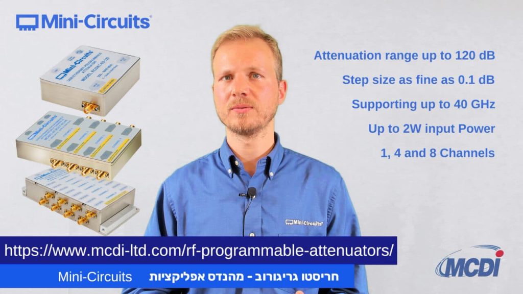
How to save time with Programmable Attenuators Hristo Grigorov – Applications Engineer, Mini-Circuits Israel – MCDI Performing sensitivity tests on RF receivers can be challenging, time-consuming, and prone to issues using the traditional method. To create the sensitivity test setup, you will usually need to create a physical separation between the transmitter and the receiver. […]


