High-Q Ceramic Resonator Filters for GNSS Applications
Giri Krishnamurthy, Mini-Circuits Engineering
Boris Benger, Mini-Circuits Applications
Introduction: The History & Modern Uses of GNSS Applications
GNSS (Global Navigation Satellite Systems) has become an increasingly prevalent RF application for both military and consumer use. Early GNSS technology, or location-based services (LBS), was developed exclusively for military use and operated with a margin of error of about 10-yards (9.14m), which was sufficient at the time, but limited its suitability for end uses requiring a higher degree of precision. In the time since the first launch of GPS more than 40 years ago, the evolution of the technology has improved precision to the order of 2-3 yards (1.83-2.74m). This advancement of the technology combined with significant miniaturization and cost reduction of LBS-enabled devices has opened up a large and growing commercial market for GNSS services. For example, GNSS is now used in the agricultural market to calculate statistics for weather, soil conditions, and crop health to help farmers maximize their yields and profits. Such innovations have stimulated demand for components that support military, industrial and consumer applications.
Due to the geostationary nature of GNSS, the various constellations each serve specific geographic regions. The United States constellation known as GPS (Global Positioning System) was the first of many to follow. Because the GPS system hovers above North America, and the signal will only reach those in America, Canada and Mexico, additional GNSS systems were launched subsequently to serve other regions of the globe. Some of these additional systems include Galileo over Europe, GLONASS (Global Navigational Satellite System) over Russia, and BeiDou (Compass) over China.
The satellites in these systems each transmit signals over L-band frequencies (L1, L2 and L5) that are picked up by the receiver in LBS-capable devices on Earth. The receiver accepts the incoming carrier frequencies from four satellites, and takes the coordinates from each in order to determine its current position in relation to the programmed destination.
Design Requirements
The L1, L2 and L5 bands function at low frequencies in the 1-2 GHz range, which makes them accessible and relatively cheap to operate within. As a result, this region of the spectrum is also occupied by multiple application bands for other communication systems. The dense development of L-band frequencies creates an increased risk of interference between different system bands. In GNSS systems, that interference can result in an immediate data error that will present itself either as an absence of information or as incorrect information.
For these reasons, when selecting filters for GNSS applications, it is important to choose a filter that is capable of high rejection with high selectivity or “sharp skirts” on an insertion loss vs. frequency graph. Narrow bandwidths are ideal for L-band applications where spectrum allocations are crowded, and low insertion loss is important for receiving the relatively weak signals transmitted from satellites to receivers on Earth.
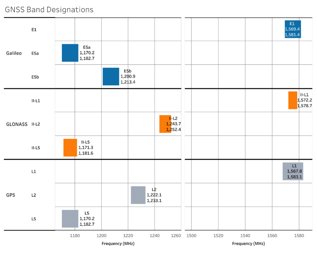
GPS, Galileo and GLONASS often share center frequencies in the L1, L2 and L5 bands allowing interoperability for LBS-enable devices between regions, although the bandwidths within each system vary. GPS generally has the widest bandwidth (approximately 15 MHz) compared to Galileo and GLONASS. Because each constellation is geographically separated from the others, there is no risk of interference between the different systems while occupying the same center frequency.
This interoperability is convenient both for filter designers and end users. A GPS filter meant to capture a frequency range in the L1 band, for example, will be able to encompass the narrower bandwidths of Galileo’s E1 band and GLONASS’s II-L1 band. This overlap allows one bandpass filter to be used in multiple GNSS systems and gives the user greater value and mobility with a single device.
Choosing the Right Filter Technology
Several filter technologies are potentially capable of meeting the requirements for GNSS applications. Ideally the filter needs to have a high Q value to prevent interference from adjacent signals and low insertion loss to preserve the integrity of relatively weak incoming signal. A cavity filter offers the highest Q value of practically any filter technology as well as low insertion loss. However, cavity filters are typically large and expensive. These practical limitations preclude their suitability for most real-world GNSS applications in which both size and cost are important factors.
L-C lumped element filters are generally smaller and more cost effective. In theory, they are capable of achieving deep rejection with very high selectivity, but this might require designing in nine or ten poles in the filter response. Although more poles will create high rejection and sharp skirts, this approach comes with a compromise on insertion loss on the order of roughly 5-7 dB which would degrade the sensitivity of the receiver.
Ceramic resonator filters, by contrast, can achieve high rejection and selectivity with much lower insertion loss (typically 1.5 dB or better) than L-C filters with comparable rejection performance. Although they are slightly larger than L-C filters, ceramic resonator filters are still an acceptable size and cost for GNSS application requirements. This combination of performance, size and cost makes ceramic resonator filters an ideal solution for use in GNSS applications.
Ceramic Resonator Filters and Diplexers for GNSS Applications
Mini-Circuits offers a broad range of ceramic resonator filters specifically designed for GNSS applications, including both off-the-shelf models and custom designs. Our ceramic resonator filters are designed with high Q resonators that provide narrow passbands with low insertion loss ranging from 0.9 dB to 3.0 dB. They boast excellent rejection and selectivity as well as low profile packaging for dense system layouts. They offer excellent temperature stability and rugged construction, making them suitable for critical applications in harsh operating conditions.
For systems with special requirements, Mini-Circuits’ applications department can advise on solutions to accommodate additional screening, qualification, and custom designs. For example, stopband rejection of standard models can be further extended by cascading LTCC filters in series. Mini-Circuits also has the design and production capability in house to make passband or bandwidth modifications of existing filters or any other customization on demand.
Below are just a few examples of standard, off-the-shelf ceramic resonator band pass filters recommended for GNSS applications:
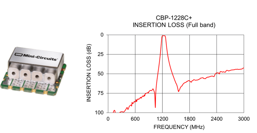
- CBP-1228C+ (1217-1238 MHz) is a narrow band filter with low insertion loss, 1.3 dB Typ. It works in the GPS L2 band (1215- 1239.6 MHz).
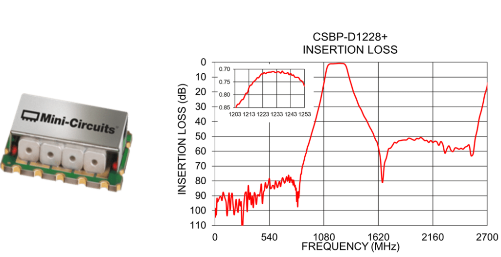
- CSBP-D1228+ (1203-1253 MHz) operates with low pass band insertion loss of 0.9 dB (Typ.) and is suitable for GLONASS G2 band (1237-1254 MHz).
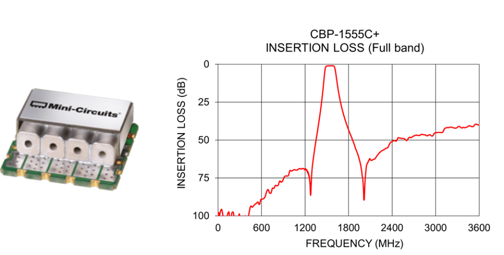
- CBP-1555C+ (1525-1585 MHz) works in the GPS L1 band (1563-1587 MHz). It provides low insertion loss of 1.1 dB Typ.
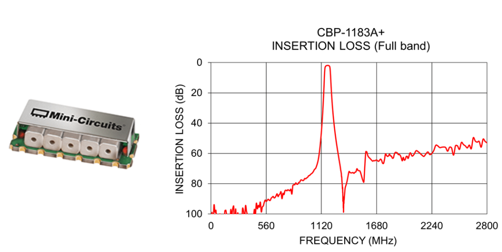
- CBP-1183A+ (1165-1201 MHz) is a high selectivity, low insertion loss filter that can be used at the GPS L5 band (1164-1189 MHz) and Galileo E5a band (1164-1189 MHz).
In addition to ceramic resonator filters, Mini-Circuits offers diplexers for GNSS applications that provide the same benefits and options for customization. The same low insertion loss and high selectivity observed in Mini-Circuits’ ceramic filters can be expected from Mini-Circuits’ diplexers in both surface mount and connectorized packages:
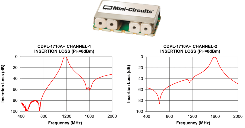
- CDPL-1710+ is an SMT diplexer with channel-1 operating at 1176 MHz (GPS L5 band and Galileo E5a band) and channel-2 operating at 1590 MHz (Galileo E1 band).
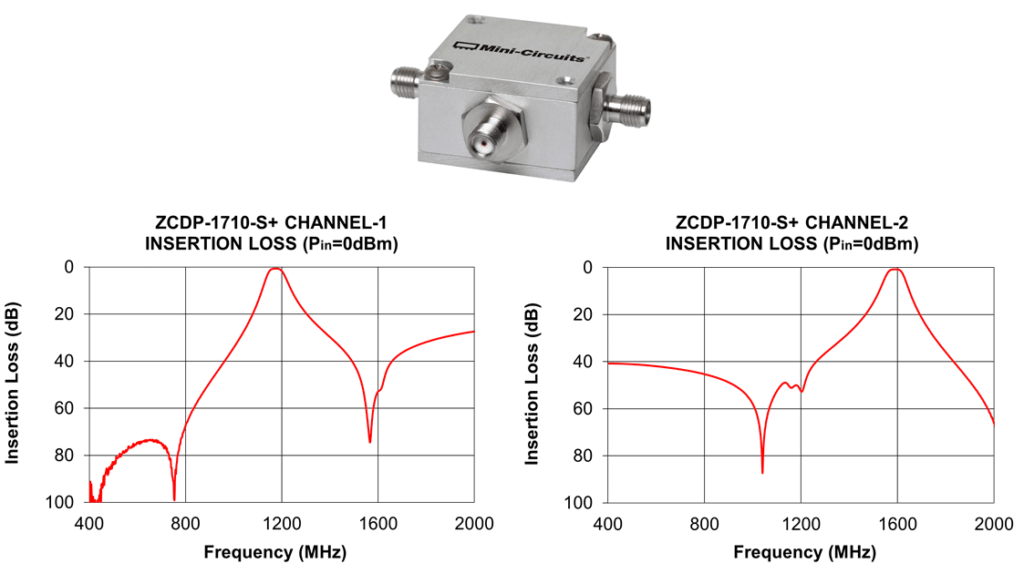
- ZCDP-1710A+ is CDPL-1710A+ in a connectorized package.
Listing of Mini-Circuits Ceramic Resonator Filters for GNSS Applications
Bandpass Connectorized Filters:
Model Number | Passband F1 (MHz) | Passband F2 (MHz) | Stopband F3 (MHz) | Rejection @ F3 (dB) | Stopband F4 (MHz) | Rejection @ F4 (dB) |
ZX75BP-1450-S+ | 1320 | 1580 | DC-1100 | 46 | 2000-2500 | 54 |
ZX75BP-A1060-S+ | 1015 | 1105 | DC-880 | 25 | 1350-4000 | 30 |
ZX75BP-A1230-S+ | 1160 | 1300 | DC-950 | 30 | 1670-3500 | 20 |
ZX75BP-B1230-S+ | 1120 | 1340 | DC-940 | 25 | 1750-3500 | 20 |
ZX75BP-B1280-S+ | 1160 | 1400 | DC-955 | 40 | 1700-2200 | 40 |
Bandpass Surface Mount Filters:
Model Number | Passband F1 (MHz) | Passband F2 (MHz) | Stopband F3 (MHz) | Rejection @ F3 (dB) | Stopband F4 (MHz) | Rejection @ F4 (dB) |
CBP-1000F+ | 900 | 1100 | DC-790 | 20 | 1260-1800 | 20 |
CBP-1023A+ | 1005 | 1041 | DC-970 | 20 | 1075-2400 | 20 |
CBP-1034C+ | 978 | 1090 | DC-790 | 20 | 1400-2000 | 20 |
CBP-1060Q+ | 1030 | 1090 | 500-930 | 20 | 1190-1400 | 20 |
CBP-1062C+ | 960 | 1164 | DC-735 | 20 | 1620-1900 | 20 |
CBP-1090C+ | 1060 | 1120 | DC-955 | 20 | 1255-2200 | 20 |
CBP-1120F+ | 1020 | 1220 | DC-880 | 20 | 1420-2000 | 20 |
CBP-1170C+ | 1110 | 1230 | DC-900 | 20 | 1560-2200 | 20 |
CBP-1183A+ | 1165 | 1201 | DC-1130 | 20 | 1235-2800 | 20 |
CBP-1228C+ | 1217 | 1238 | DC-1140 | 20 | 1330-3000 | 20 |
CBP-1250C+ | 1215 | 1285 | DC-1055 | 20 | 1510-2500 | 20 |
CBP-1260C+ | 1200 | 1320 | DC-1025 | 20 | 1640-2450 | 20 |
CBP-1280C+ | 1170 | 1390 | DC-950+ | 20 | 1850-2450 | 20 |
CBP-1280F+ | 1160 | 1400 | DC-1000 | 20 | 1570-2100 | 20 |
CBP-1300A+ | 1200 | 1400 | DC-1040 | 20 | 1640-3100 | 20 |
CBP-1307C+ | 1215 | 1400 | DC-1000+ | 20 | 1820-2500 | 20 |
CBP-1320Q+ | 1280 | 1360 | 900-1170 | 20 | 1490-20000 | 20 |
CBP-1350C+ | 1300 | 1400 | DC-1125 | 20 | 1665-2700 | 20 |
CBP-1400E+ | 1320 | 1480 | DC-1150+ | 20 | 1600-2400 | 20 |
CBP-1400F+ | 1300 | 1500 | DC-1090+ | 20 | 1740-2450 | 20 |
CBP-1423AF+ | 1333 | 1513 | DC-1113 | 60 | 1669-2600 | 55 |
CBP-1450F+ | 1320 | 1580 | DC-1150 | 20 | 1775-2350 | 20 |
CBP-1475E+ | 1375 | 1575 | DC-1230 | 40 | 1750-2600 | 40 |
CBP-1490A+ | 1465 | 1515 | DC-1430 | 20 | 1550-3000 | 20 |
CBP-1538J+ | 1518 | 1559 | DC-1390 | 20 | 1750-3000 | 20 |
CBP-1555C+ | 1525 | 1585 | DC-1415 | 20 | 1700-3600 | 20 |
CBP-1598AF+ | 1505.5 | 1690.5 | DC-1264 | 60 | 1888-2900 | 60 |
CBP-1630F+ | 1500 | 1760 | DC-1320 | 20 | 1960-2600 | 20 |
CBP-1645J+ | 1616 | 1675 | DC-1500 | 20 | 1850-3000 | 20 |
CBP-A1060C+ | 1015 | 1105 | DC-865 | 20 | 1350-2250 | 20 |
CBP-A1230C+ | 1160 | 1300 | DC-950 | 20 | 1670-2400 | 20 |
CBP-B1230C+ | 1120 | 1340 | DC-980 | 20 | 1750-2350 | 20 |
CSBP-B1300-75+ | 1210 | 1390 | DC-1080 | 20 | 1545-2500 | 20 |
CSBP-D1189+ | 1130 | 1246 | DC-950 | 20 | 1550-2400 | 20 |
CSBP-D1228+ | 1203 | 1253 | DC-1020 | 20 | 1425-2500 | 20 |
Connectorized Diplexers:
Model Number | Passband (MHz) | Passband IL (dB) | Rejection (dB) | Return Loss (dB) | Crossover Isolation (dB) |
ZCDP-1710-S+ | 1590 | 0.8 | 40 @ 1176 | 11 | – |
ZCDP-1710-S+ | 1176 | 0.8 | 50 @ 1590 | 11 | – |
Surface Mount Diplexers:
Model Number | Passband (MHz) | Passband IL (dB) | Rejection (dB) | Return Loss (dB) | Crossover Isolation (dB) |
CDPL-1710A+ | 1176 | 0.8 | 50.6 @ 1590 | 10.9 | – |
CDPL-1710A+ | 1590 | 0.8 | 39.7 @ 1176 | 10.9 | – |


