Stabilizing Multiplier Chain Conversion Efficiency with Reflectionless Filters
Overview
Frequency translation devices such as multipliers and dividers are used to convert frequencies from lower spectrum regimes to higher frequencies, and vice versa. As these devices are intrinsically non-linear, they generate spurious harmonics, which are often filtered to prevent harmonics from appearing in-band. Using conventional, reflective filters creates an undesirable scenario where the out-of-band harmonics are reflected back to the multiplier. The multiplier is also affected by the reactive loading exhibited by a reflective filter at harmonic frequencies (see Figure 1). Given that multipliers have poor output return loss, this combination of effects leads to large ripples in the conversion efficiency of a multiplier chain, and hence, susceptibility to environmental factors.
This issue can be solved by leveraging the unique capabilities of reflectionless filters. To demonstrate this solution, an experiment was conducted with a doubler test circuit and a 4X multiplier chain (see Figure 2). Each experiment was conducted using comparable reflective and reflectionless filters, and the results were then analyzed.
Test Setup
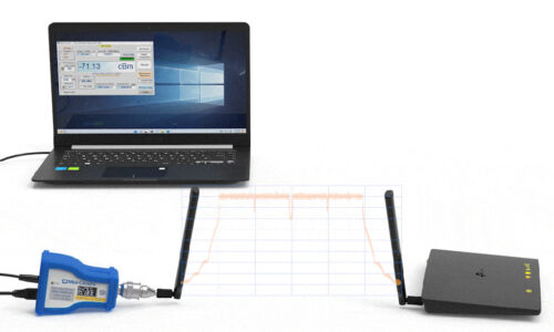
The tests were conducted using an Agilent E8257D PSG signal generator and an Agilent U2000A power meter. The doubler used in all tests was a Mini-Circuits ZX90-2-36-S+. The second doubler in the 4X multiplier chain was a KSX2-24+. The amplifier used in the multiplier chain was a GALI-39+. The conventional filter was a Mini-Circuits VLF-6400+, and the reflectionless filter was a Mini-Circuits XLF-662M+. Each test was done using four different lengths of interconnect between the connectorized doubler and filter: no cable, a 6-inch coaxial cable, a-12 inch coaxial cable, and a 36-inch coaxial cable. An image of the test setup of the doubler-filter pair is shown in Figure 3.


Results
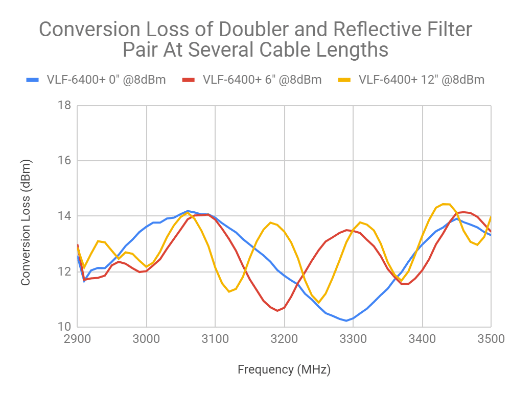
Results of the two experiments are shown in Figures 4, 5, 6 and 7. Figure 4 shows the conversion loss of a doubler-filter pair at various power levels with a reflectionless filter (top) and a reflective filter (bottom). The plots in Figure 4 show that even at nominal power levels for the doubler, the reflective filter’s out-of-band impedance mismatch leads to reflections of the harmonics, especially the 3rd harmonic, which creates greater conversion loss ripple. Figure 5 exaggerates this point by replicating the same experiment, but with a longer transmission line length (6 inches) between the filter and doubler, allowing for greater development of standing waves. Figure 5 shows that the reflectionless filter (top) is able to effectively attenuate the out-of-band reflections with almost no additional conversion loss ripple, while the reflective filter exhibits standing wave effects that worsen with the length of the transmission line used.

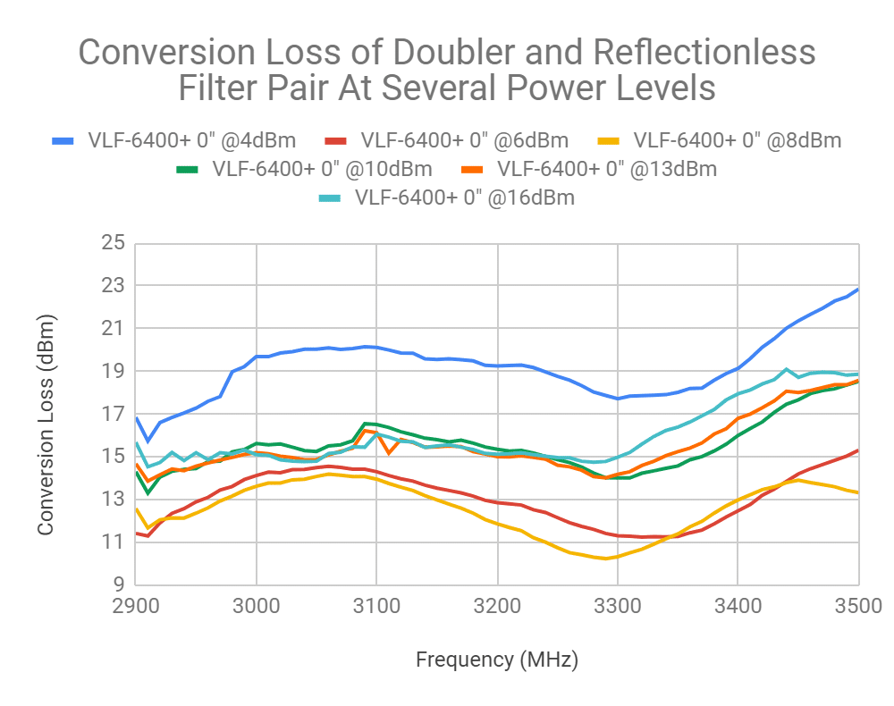

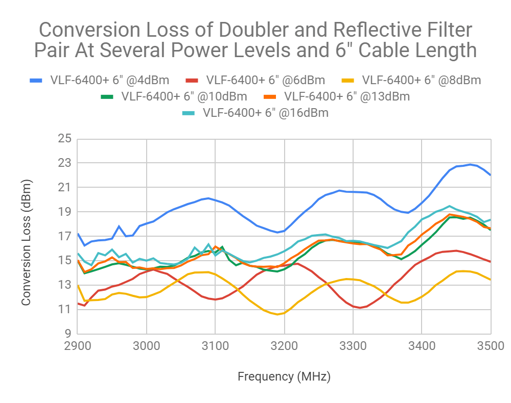
Figure 6 captures the susceptibility of a doubler-filter pair to effects created by filters with out-of-band impedance mismatch that can worsen the standing waves. Even in the worst case experimental example (a 36” transmission line extension), the reflectionless filter (top) only develops a marginal conversion loss ripple, while the ripple of the reflective filter (bottom) is over 2 dB. A side-by-side comparison of the conversion loss ripple for both the reflective and reflectionless filter is provided in Figure 7 (top).
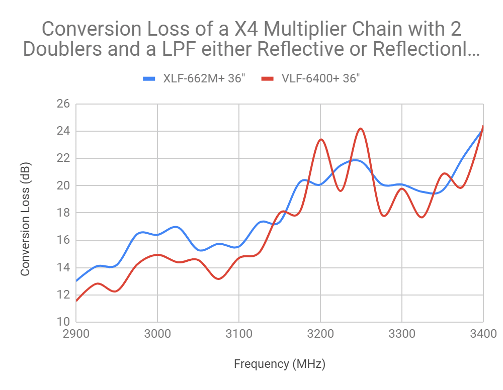
Lastly, in Figure 7 (bottom) an X4 multiplier chain is tested using two doublers with a filter after the first doubler. This plot shows that the conversion loss ripple under worst-case conditions (extended transmission line) is greater for the reflective filter than the reflectionless filter by over 3 dB peak-to-peak. In order to achieve comparable conversion loss ripple with a conventional filter to that of a reflectionless filter, a much higher power amplifier and an extra attenuator would be necessary to push the doublers well into saturation and mitigate the standing wave generated by the higher power level. In longer multiplier chains, the reflective nature of conventional filters may degrade conversion loss flatness even further, which necessitates careful selection of amplifiers and attenuators distributed throughout the multiplier chain, adding size, cost and complexity to the system. By contrast, a well-chosen amplifier with a reflectionless filter can achieve flat conversion loss efficiency while minimizing cost, size and the need for extra components.


If you have a specific application and have questions about how reflectionless filters can improve your system performance, contact our applications team: [email protected]
Browse Mini-Circuits’ full selection of reflectionless filters.


