Advanced Microwave Amplifier Models for Advanced Design System Simulations

Mobile and wireless communication has seen phenomenal growth over the past two decades. Faster communication with higher data rates has been the driving factor. To achieve this, the RF front end components have been continuously improved to meet the linearity and power requirements and a range of wireless standards have emerged, based on variations in frequency, modulation and power level requirements. The 0.7 GHz to 6 GHz band has been the mostly widely used frequency range for mobile and wireless communications using different standards such as GSM, CDMA, WCDMA, LTE, WLAN and WiMAX. The evolving 5G standard is pushing frequency ranges for emerging commercial systems upward to mm-wave frequencies as high as 86 GHz! Still, the bulk of near term 5G developments will likely be at the proposed bands of 28GHz and below.
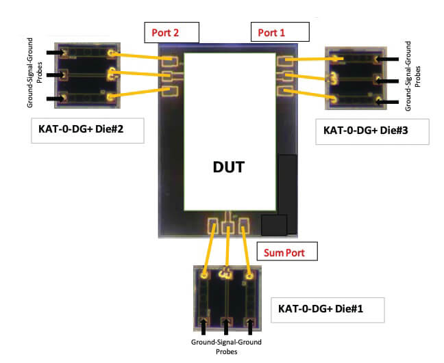
MMIC Die Testing Made Easy with Ultra-Wideband 0 dB Attenuator (Thru-Line) Dice

Microwave hybrid circuitry is generally built by integrating several discrete dice via wire bonding. Circuit designers are faced with the task of predicting the performance of hybrids, which comes with some specific challenges.
A Practical Approach to the Design and Implementation of Scalable, High-Performance, Custom SMT Packages for mmWave Applications

After many years of research and development, electrical engineers, physicists, mathematicians and scientists have come to realize the benefits of operating communications systems at higher frequencies. Some of the most notable advances stemming from this research include: smaller circuit implementations for the same functionality; improved antenna gain for a given antenna size; and dramatic increases in data-carrying capacity. However, numerous challenges remain in implementing high-frequency circuits under real-world constraints. Among the non-trivial problems, packaging stands out.
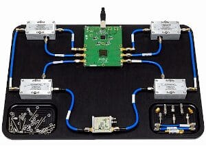
Mini-Circuits Bridging the Gap Between the Classroom and the Lab

With a history that dates back 50 years, Mini-Circuits is one of the most recognizable names in the RF/microwave industry. Known as a supplier of high-frequency components, Mini-Circuits offers an enormous number of products, which includes the likes of amplifiers, filters, mixers, and couplers, just to name a select few.
Line Stretchers Ease VCO Load-Pull Testing

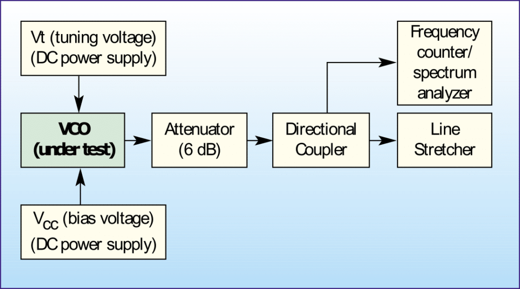
Voltage Controlled Oscillators (VCOs) are normally designed for operation in an ideal 50 ohm environment. However, the actual load that these oscillators must drive are considerably different. It is a standard industry practice to measure frequency variation when the VCO output realizes a load with 12dB return loss (for all possible phase angles). This is usually performed as a manual measurement and is very time consuming. It may take a skilled technician several minutes to several hours. Fortunately, with the development of a novel electronic line stretcher from Mini-Circuits, these once tedious tests can now be executed quickly and a automatically.
Achieving First-Spin Success in LTCC Components with Advanced Material Simulation Models

Since the advent of Network Synthesis Theory at the turn of the last century, filter designers have been developing ever more sophisticated solutions to translate polynomial transfer functions into working, physical components.
Adapting Non-Sealed Surface Mount Parts for Hi-Rel Customer Assembly Processes

The perfect integration of a product within the customer’s assembly process can be just as critical to the success of that product asthe electrical performance. Mini-Circuits and many RF/microwave component manufacturers build surface mountcomponents that are soldered onto customers’ PC boards using a reflow process. Following reflow, the board must be cleaned to remove solderballs, flux, salt deposits and other debris. While a number of cleaningmethods exist, the industry – and especially manufacturers of equipment for military and other hi-rel applications – have gravitated towards aqueous wash. A conformal coating is then applied to protect the circuit from moisture and other adverse environmental conditions. This process poses unique challenges for the integration of surface mount parts into customer assemblies, particularly components with open and semi-sealed case styles.
The Mystery behind MSL 1, 2, 3

Semiconductor non-hermetic packages have the tendency to absorb moisture. During the surface-mount solder reflow process, moisture trapped in the package will vaporize when heat is applied. The expansion of this trapped moisture creates internal stress, which can cause damage to the non-hermetic package. The damage can take the form of internal separation between the plastic and die or metal frame, wire bond damage, die damage or internal cracks.
AS9100 Transition Drives Technical Excellence

Technical excellence at Mini-Circuits is coming into sharper focus as we approach the fifth decade since our founding by Harvey Kaylie in 1969. This focus has been emphasized in our current initiative to recertify our quality management system (QMS) to the new revision of AS9100. As you may expect, Mini-Circuits places the highest priority on product quality, and this has had many benefits for us and our customers. Our customer returns have been consistently below 10 PPM over the past year, and we will continue finding ways to drive this metric even closer to zero.
Solid State Switching for Next Generation Wireless Test Applications

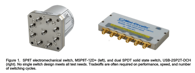
Rapid growth in the number of connected devices for next generation wireless applications is driving demand for faster, more innovative, and more cost-effective test solutions. The need for reduction in cost and improvement in test throughput is found both at the design verification stage as well as in high-volume production testing. Test engineers are looking for ways to reduce the number of device-under-test (DUT) connections and enable testing of multiple DUTs in parallel from a single test station. This is most often achieved by configuring RF switches in a switch matrix to automate the routing of test signals. This article will explore some of the key differences between the types of switches used in test applications. Switch matrix configurations will be discussed, and a real world switch matrix for a high-volume telecom test application described in detail.


