Model: ZYSWA-2-50DR+ (Redesigned Model)
1. Purpose
To validate the extended life performance of the Mini-Circuits mechanical switch product line in the defined environment under defined operating conditions.
2. Scope:
- MSP2T-18XL
- MSP2TA-18XL
- MTS-18XL-B
3. Background:
Prior to developing our mechanical switch, Mini-Circuits purchased a significant quantity of mechanical switches for use in our production test facilities. These switches utilized a combination of springs and solenoids to accomplish the switching. Most operated for less than 1 million cycles, or approximately 50 days in our production environment. This turnover prompted Mini-Circuits to develop our own design to address the short operating life, long lead times, and high cost of using commercially available mechanical relay switches.
4. Design Approach
Design Objective: Develop a long life mechanical switch.
Design Criteria:
- Eliminate the use of any springs.
- Select combinations of materials based upon compatibility and ability to mate with limited wear.
- Simplicity of design with the minimum number of components possible.
- Cost effectiveness to meet internal and external market demands.
5. Tests Performed
5.1 Life Testing
In a production test environment, a failure is very important. When using commercially available mechanical relays, we observed a number of cases where “good” products failed as a result of a bad switch in our test system.
It was commonly believed that a mechanical switch has “failed” when it fails to switch states (was closed when expected to be open, or open when expected to be closed), i.e. catastrophic failure. We learned that a mechanical switch will actually show many cycles of degraded performance prior to reaching catastrophic failure. For customer use purposes, the number of failed switching cycles is a more meaningful criteria for determining the “failure” of a mechanical switch. For example, many commercially available mechanical switches are specified at one-million cycle life expectancy; however, we have seen that these switches often exhibit failed performance starting at 800K cycles. In a test environment, every failed performance cycle can mean a rejected good DUT.
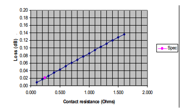
To determine if a switch has failed life test, we define “life test failure” as an accumulation of individual cycle performance failures. The failure criteria of any one performance cycle is one that measures DC resistance exceeding 240 mΩ. That is equivalent to an increase in RF insertion loss at low frequencies of 0.021 dB (see chart below).
The Mini-Circuits criteria for mechanical switch life test failure is a unit which passes both of the following conditions:
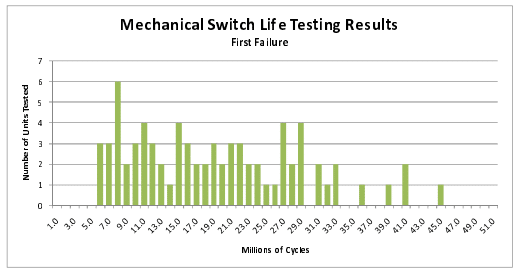
1. First 10 cumulative cycle failures occur at greater than 5 million total switch cycles.
(equals 2 DPPM)
– and –
2. Cumulative of 1000 cycle failures occurs at greater than 10 million total switch cycles.
5.2 Sleep Mode Testing
Sleep testing validates the ability of a mechanical switch to remain in a fixed state for an extended period of time, and still switch reliably to another state when energized. This parameter is a result of applications where mechanical relay switches are used to switch-in redundant paths in the event of a failure in the main path. A switch functioning in this mode is often referred to as operating in “sleep mode”.
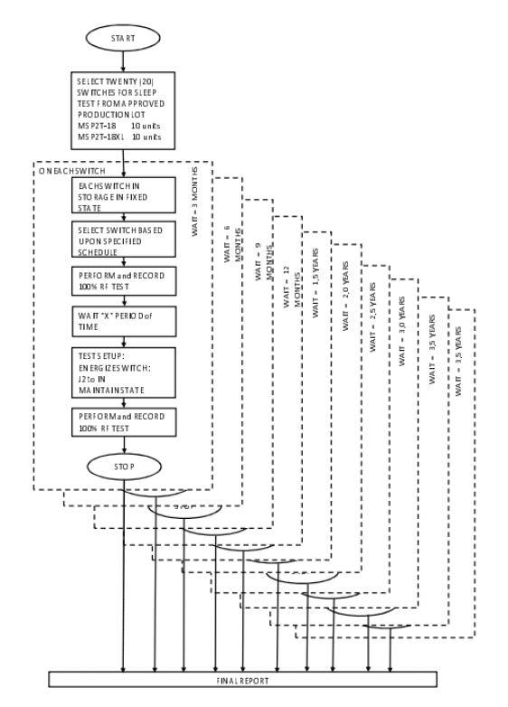
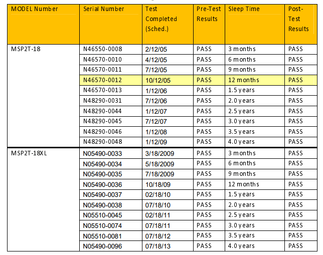
Mini-Circuits’ has and continues to test switches in this mode of operation. Sets of 10 switches are stored in a fixed state over a period a four (4) years. At specific intervals, switches are removed and tested for their ability to “switch” after the period of inactivity.
6. Switch Tune-Up
Even though the life of the Mini-Circuits switches is far greater than any other switch on the market today, even our switches will fail – at some point. Mini-Circuits unique construction makes it very practical to clean the switch contact assembly enabling switch performance recovery for extending the switch life to well over 100 million cycles.
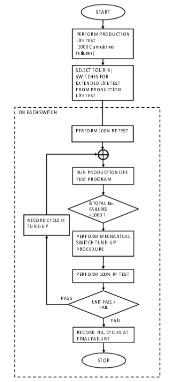
Mini-Circuits also validated the effectiveness of the “tune-up” on our mechanical switches, subjecting switches to extended life testing with “tune-ups” after any switch reached 1000 cumulative failed cycles. We achieved a total life cycle of greater than 300 million cycles.
7. Production Life Testing
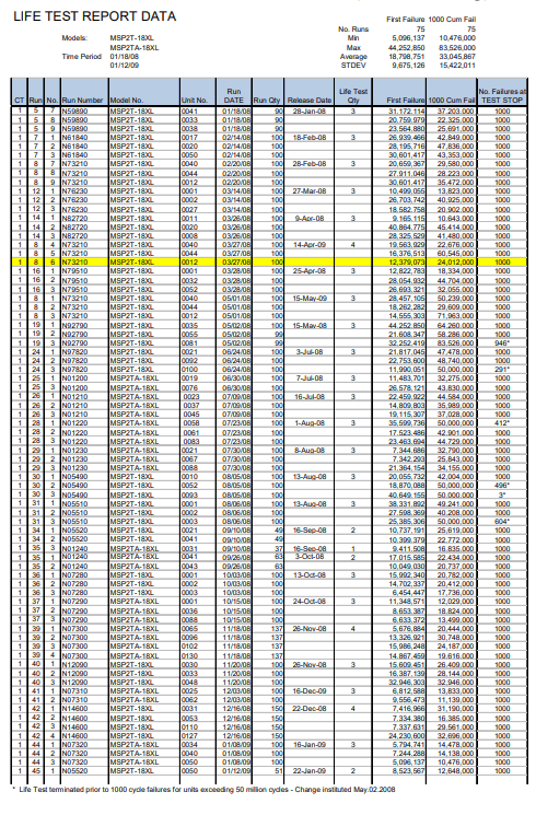
It is a Mini-Circuits internal quality requirement that each production lot of mechanical RF switches be subjected to sample life testing prior to lot acceptance. On each production lot, a minimum of two (2) switches are randomly selected and subjected to the same DC life test as outlined above. All units are required to pass the First Failure and the Cumulative Failure criteria for lot acceptance. Data is recorded on all lots and a sample summary is included herein.
Production Life Test data is used in this report as basis for life testing. (referred herein in TEST 1: Life Testing – without tune-up).
8. Test Summary
8.1 TEST 1: Life Testing (Without Tune-Up)
Seventy-five (75) switches tested over a period of 1 year.
Model: MSP2T-18XL and MSP2TA-18XL.
Test Results:

8.2 TEST 2: Extended Life Testing – After Tune-Ups
Five (5) switches tested.
Test Results: All units exceed 300 million cycles after.
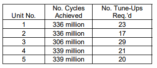
Testing terminated after 300 million cycles (units show no permanent wear and continue to operate).
8.3 TEST 3: Sleep Mode Testing
20 units tested (10 units MSP2T-18, 10 units MSP2T-18XL).
All units energized in state”1.”
Units energized to state “2” over 4 years.
All units successfully switched to state “2.”
9. Test Methods and Conditions
9.1 Life Tests (Tests 1 and Tests 2):
Test Conditions:
- Contact resistance is measured at DC, between the probes of the connectors in the ON path in every cycle.
- DC current = 2 mA.
- The cycle time is ~110 milliseconds PORT X to PORT Y.
- All tests performed at room temperature (+25C).
Failure Criteria:
Individual Switch Cycle Failure: Contact resistance >240 mΩ max.
Switch Assembly Failure Recordings:
a) First Failure: The first time a contact exhibits greater than 240 mΩ DC resistance.
b) Cumulative Failures: A cumulative of 1000 cycles in which the DC resistance measures greater than 240 mΩ
9.2 Sleep Time Test
Mini-Circuits switches have passed four-year sleep time test. Sleep time defines the period over which switch is not energized and hence not switched.
Test Conditions:
- Frequency 1, 100 & 1000 MHz at low RF power, 0 dBm.
- Twenty (20) switches randomly selected from production lot:
MSP2T-18 10 pcs.
MSP2T-18XL 10 pcs.
- RF test before sleep test.
- RF test after sleep test.
Failure Criteria:
- Must work when switched for the first time and meet specifications.
10. Detailed Test Results – TEST 1: Life Tests (Without Tune-Up)
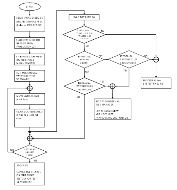
10.1 Test Process – TEST 1 Life Test (Without Tuneup)
Life test data is derived from results of production life test process, performed as follows:
10.2 DC Resistance Measurement
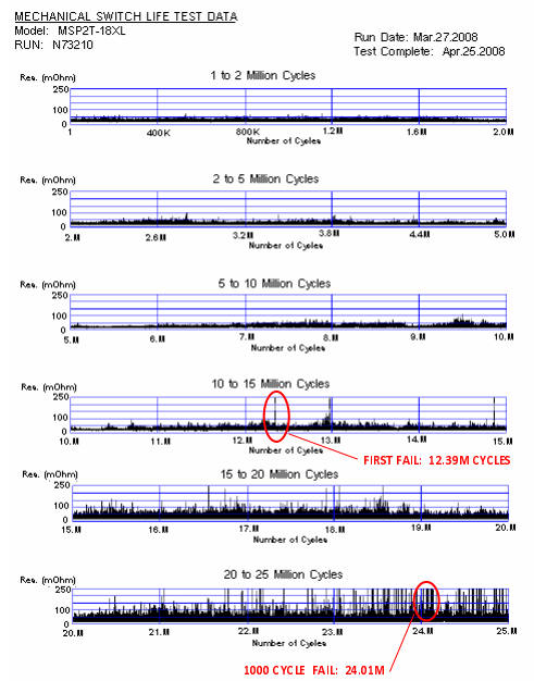
DC Resistance is measured at each switching cycle for each port on life test units. Data is collected and reviewed on a daily basis. Life test units are tested to failure; i.e. greater than 1000 cumulative cycles with DC resistance >240mΩ.
Typical DC life test data on a single unit is presented below in Figure 3 below:
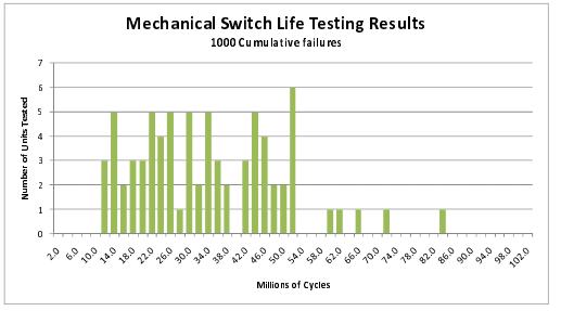
10.3 75 Unit Data Distribution – TEST 1: Life Tests (Without Tune-Up)
First Failure – Production Distribution Results:
1000 Cumulative Failures – Production Distribution Results:
10.4 Detailed Test Data – TEST 1: Life Tests (Without Tune-Up)
11. Detailed Test Results – TEST 2: Extended Life Tests (With Tune-Up)
11.1 Test Process – TEST 2 Extended Life Test (With Tune-Up)
11.2 Test Results- TEST 2 Extended Life Test (With Tune-Up)
Run: E39070 Start Date: October 19th, 2006 End: March 3rd 2008.

12. Detailed Test Results – TEST 3: Sleep Testing
12.1 Test Process – TEST 3 Sleep Test
12.2 Test Results – TEST 3 Sleep Tests
13. Conclusion
Due to the design approach as outlined in section 4, for all practical purposes, these switches do not wear out and have a lifetime far exceeding switches commercially available. They have the ability to be used in excess of 300 million cycles with periodic tune-up, meeting all electrical performance as outlined in our catalog datasheet.
14. Appendix RF Test Data
Typical test data taken on switch, BEFORE and AFTER sleep test.
14.1 Before Sleep Test Data
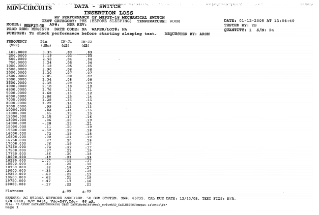
Insertion Loss – RUN N46570 – S/N 0012 (D/C 0451).
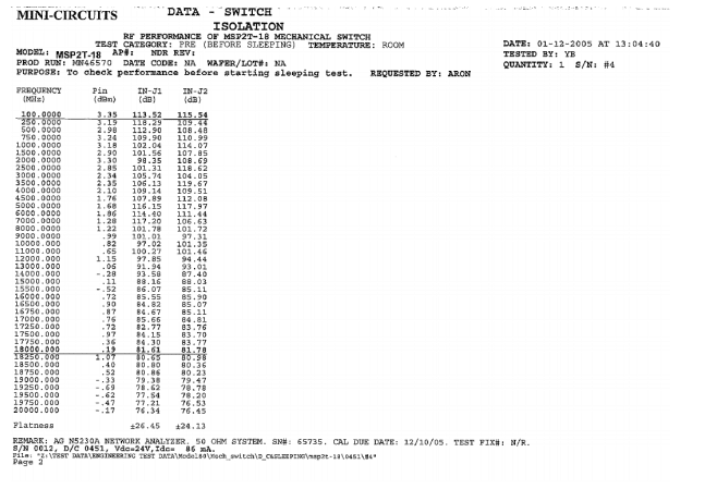
Isolation – RUN N46570 – S/N 0012 (D/C 0451).
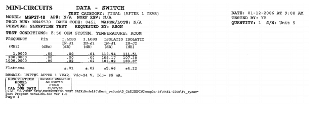
Insertion Loss and Isolation – N46570 – S/N 0012 (D/C 0451).
View all RF Switches


