Understanding RF Power Amplifier Classes

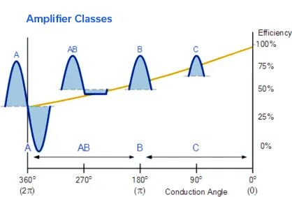
Power amplifiers (PAs) boost input signals using different amplification schemes depending upon application requirements and the nature of the signals to be boosted. Signals may be continuous wave (CW) or many forms of pulsed waveforms, with different pulse widths and duty cycles. Different signal types have different amplification needs in terms of output power, gain, efficiency, linearity, and other performance parameters.
Extending the Performance and Frequency Envelope for QFN Packaging Technology

High-performance, millimeter-wave (mmW) Monolithic Microwave Integrated Circuit (MMIC) products and cost-effective surface mount lead-frame-based packaging typically don’t come up in the same conversation, and for good reason. Just two to three years ago, it was difficult to conceive of operating at frequencies above 20 GHz without considering an expensive, open cavity, High Temperature Co-fired Ceramic (HTCC) package or resorting to more bespoke chip and wire assemblies.
Choosing the Right RF Coaxial Cable Assembly for Your Application

Selecting the right RF/microwave cable assembly can be a confusing task considering the variety of products on the market and the multiple characteristics of each. Adding to the challenge, many products don’t lend themselves to a straightforward, “spreadsheet” comparison. This guide was written to go beyond the spec sheet and help you find the right cable for your needs more quickly and more knowledgeably. We will review the different categories of RF cables and their attributes and provide some guidelines on how to prioritize parameters for your application. Note that we omitted fundamental RF theory because much has been written on that subject and this is meant to be a practical resource for engineers in the field rather than a study guide. We also omitted corrugated and CATV coaxial cable as those are typically used for niche applications.
Reflectionless Filters Minimize Switching Transients in Wideband ADCs

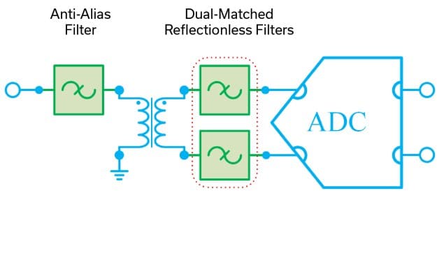
Designers are finding new techniques to improve system performance with Mini-Circuits’ patented reflectionless filters all the time. Among these, supplementing anti-alias filters in wideband ADCs to minimize the effect of switching transients has emerged as a popular use case.
Directional Couplers: Their Operation and Application

Directional couplers are important devices in RF systems. Their ability to sample either the forward or reverse direction of signal propagation allows a wide range of applications in test, measurement, monitoring, feedback and control. This note should help system designers understand the function, architecture and performance of the coupler, to select a suitable type for their particular application.
Understanding Power Splitter/Combiner Power Handling with Coherent and Non-Coherent Signals

A Power Splitter/Combiner is a passive device that can be used for two reciprocal functions: a single signal may be divided into multiple outputs, or in the opposite direction, multiple input signals are combined into a single output. In case of an N-port splitter, the input signal will be divided into N output ports. When used as an N-port combiner, the N inputs will be combined into an output signal from a single port.
Combining MMIC Reflectionless Filters to Create Ultra-Wideband (UWB) Bandpass Filters

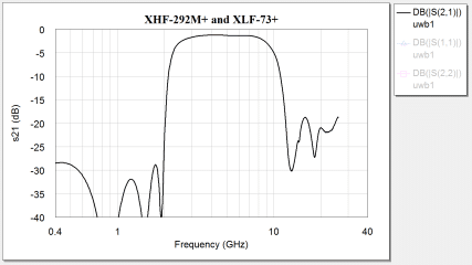
Ultra-Wideband (UWB) radio is defined as any RF technology utilizing a bandwidth of greater than ¼ the center frequency or a bandwidth greater than 500 MHz [1] [2]. While UWB has been a known technology since the end of the nineteenth century, restrictions on transmission to prevent interference with narrow-band, continuous wave signals have limited its applications to defense and relatively few specially licensed operators [1]. In 2002, the FCC opened the 3.1 to 10.6 GHz band for commercial applications of Ultra-Wideband technology, and since then UWB has become a focus of academic study and industry research for a promising variety of emerging applications. To prevent interference with neighboring spectrum allocations like GPS at 1.6 GHz, the FCC has imposed specific rules for indoor and outdoor transmission of UWB signals, limiting transmissions in the permitted frequency range to power levels of -41 dBm/MHz or less.
Demystifying Transformers: Baluns and Ununs

Baluns and ununs are essential in RF signal chains for many applications. RF balun designs are most commonly associated with core-and-wire transformers, but can also be realized through coaxial and coupled stripline technologies. The behavior of baluns and ununs was introduced in Part 1 of this series, where we established that both these devices are designed for impedance matching purposes. The major difference between them is that baluns are designed to match impedances between balanced and unbalanced circuits, whereas ununs provide impedance matching between two unbalanced circuits.
Stabilizing Multiplier Chain Conversion Efficiency with Reflectionless Filters

Frequency translation devices such as multipliers and dividers are used to convert frequencies from lower spectrum regimes to higher frequencies, and vice versa. As these devices are intrinsically non-linear, they generate spurious harmonics, which are often filtered to prevent harmonics from appearing in-band. Using conventional, reflective filters creates an undesirable scenario where the out-of-band harmonics are reflected back to the multiplier. The multiplier is also affected by the reactive loading exhibited by a reflective filter at harmonic frequencies (see Figure 1). Given that multipliers have poor output return loss, this combination of effects leads to large ripples in the conversion efficiency of a multiplier chain, and hence, susceptibility to environmental factors.
This issue can be solved by leveraging the unique capabilities of reflectionless filters. To demonstrate this solution, an experiment was conducted with a doubler test circuit and a 4X multiplier chain (see Figure 2). Each experiment was conducted using comparable reflective and reflectionless filters, and the results were then analyzed.
Demystifying RF Transformers: A Primer on the Theory, Technologies and Applications – Part 1

In essence, a transformer is merely two or more conductive paths linked by a mutual magnetic field. When a varying magnetic flux is developed within the core by alternating current passing through one conductive path, a current is then induced in the other conductive paths. This induced current is proportional to the ratio of magnetic coupling between the two conductive paths. The ratio of the magnetic coupling of the conductive paths with the core determines the induced voltage in the additional conductive paths, providing both an impedance transformation and a voltage step-up or step-down. Additional conductive paths, potentially all with different coupling ratios, may be added to realize various functions, which is why RF transformers are such varied and versatile devices used widely throughout the RF/microwave industry.


