The Basics of Orthogonal Frequency-Division Multiplexing (OFDM)
While traditional Frequency Division Multiplexing has been around for over 100 years, Orthogonal Frequency Division Multiplexing (OFDM) was first introduced by Robert W. Chang of Bell Laboratories in 1966.1,2,3,4 In OFDM, the stream of information is split between many closely-spaced, narrowband subcarriers instead of being relegated to a single wideband channel frequency.5 Single-channel modulation schemes tend to be sequential whereas, in OFDM, many bits can be sent in parallel, simultaneously, in the many subcarriers.5 So many bits can be packed onto the subcarriers simultaneously that the data rate of each subcarrier’s modulation can be much lower than that of a single-carrier architecture. Lower subcarrier data rates combined with their orthogonality make the system much less susceptible to intersymbol interference (ISI) as well. Weinstein and Ebert introduced a guard interval between symbols in 1971,4 providing better immunity to the transmission phenomenon known as multipath delay spread, which can cause high levels of ISI.4,7 The ability of OFDM to withstand high levels of frequency-selective fading is another chief advantage it has over alternative transmission schemes. OFDM finds applications in 4G/5G cellular networks, IEEE-802.11 WLANs, IEEE 802.16 WiMAX, IEEE 1901 power line communications, and even digital television and digital audio broadcasting.
In this application note we will delve into the basic characteristics of OFDM, first defining what is meant by orthogonal, then examining how OFDM systems structure their transmissions in both the time and frequency domains. We’ll touch briefly on the modulation of each of the subcarriers, then describe how some of the more familiar applications such as cellular and Wi-Fi utilize OFDM. We’ll conclude with a glimpse into the future of OFDM bandwidths and potential data rates.
Subcarriers and Orthogonality
Figure 1 shows 5 adjacent subcarriers in the frequency domain, normalized to an amplitude of 1 and a frequency separation of 1. For a subcarrier in OFDM to be orthogonal, it must be spaced from its adjacent, neighboring subcarrier(s) in such a way that the peak of each adjacent subcarrier falls exactly at its zero crossings.6 The subcarriers shown are arranged in this fashion and therefore orthogonal. It is precisely because of this frequency separation arrangement, or orthogonality that OFDM has such excellent immunity to intersymbol interference (ISI). The frequencies of the subcarriers are chosen specifically to theoretically not interfere with one another. Normally, when subcarrier spectra overlap, subcarrier interference results, except at orthogonally spaced frequencies.7 The orthogonal, overlapping signals shown in Figure 1 do not interfere with the signal recovery capability of the receiver, the receiver “multiplies (i.e., correlates) the incoming signal by the known set of sinusoids to recover the original set of bits sent.”7
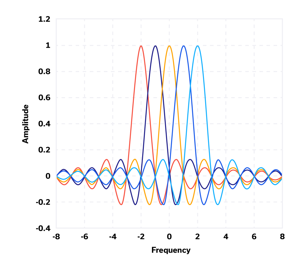
The strange spectral shape shown for an otherwise sinusoidal subcarrier (which would be an impulse in the frequency domain) is due to the fact that each subcarrier is modulated by a rectangular waveform, which yields the Sinc function in the frequency domain (after taking the Fourier transform, of course).8 Overlapping frequency domain spectra clearly leads to greater spectral efficiency, or Bits/Hz.
OFDM Modulation – Fast Fourier Transforms and Inverse Fast Fourier Transforms
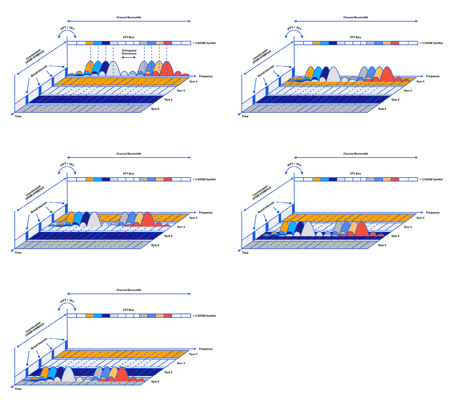
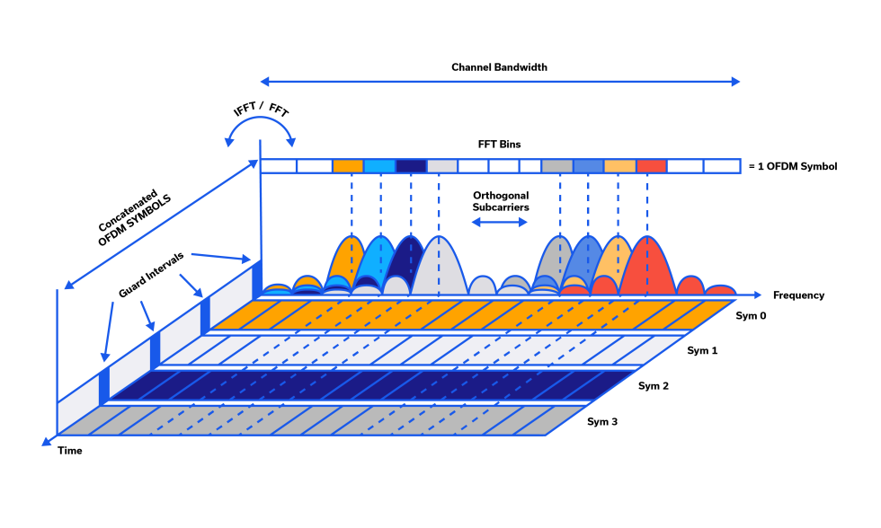
As shown in the diagram of Figure 2, N overlapping subcarriers form a symbol, and each symbol occupies a timeslot with guard intervals in between. Within each sinc function spectrum (note the magnitude of the spectrum is shown in Figure 2) is, for example a QAM constellation point (i.e. that subcarrier’s sinusoid at a specific amplitude and phase). To generate the time domain waveform to be transmitted from the frequency domain waveform in the modulator/transmitter, an inverse fast Fourier transform (IFFT) is utilized. Therefore, the transmitted waveform itself is the IFFT output, or N orthogonal sinusoids in the time domain. One of the disadvantages of OFDM is that this N-subcarrier, transmitted symbol has an exceptionally high peak-to-average power ratio (PAPR), necessitating a very linear, high power amplifier for transmission. GaN devices and envelope tracking have eased those constraints in recent years.
“At the receiver, an FFT is [performed] to process the received signal and bring it into the frequency domain which is used to recover the original data bits.”7
Multipath Performance
Multipath happens when a radio signal bounces off any obstacle that appears in its path such as natural geographic features, buildings, trees, etc. “Multipath causes the transmitted signal to be sent on two or more paths to the receiver, making it difficult for the receiver to interpret what it receives.”6 Because the wavelength of the radio frequency waves vary across the band, only some frequencies will experience degradation due to multipath. In traditional single-carrier-modulated systems, multipath can have a devastating effect for the whole frequency spectrum, affecting all of the data symbols.6
When N subcarriers are transmitted in a radio channel, it is possible that only one or several subcarriers experiences multipath degradation. Since all subcarriers transport symbols, data loss is minimal, especially since data can also be recovered through redundancy and error correction.
5G Frequency-Time Structure
It’s always interesting to dive in and find out how some of the more common waveforms are structured. Figure 3 shows a frequency-time diagram for the 5G NR structure that by default also includes LTE (it must, in essence, include LTE to be truly backward-compatible). While Figure 3 looks complex at a glance, it can be broken down as follows. The smallest segment of the frequency domain structure, represented by one block on the frequency and time axes, is referred to as a Resource Element, as shown. A Resource Block is 12 Resource Elements stitched together in the frequency domain with each on its own subcarrier, also shown on Figure 3. The structure for LTE is that a Resource Block consists of 12 subcarriers and 7 symbols (side-by-side Resource Blocks in the time domain), whereas 5G NR has no time/symbol limit.
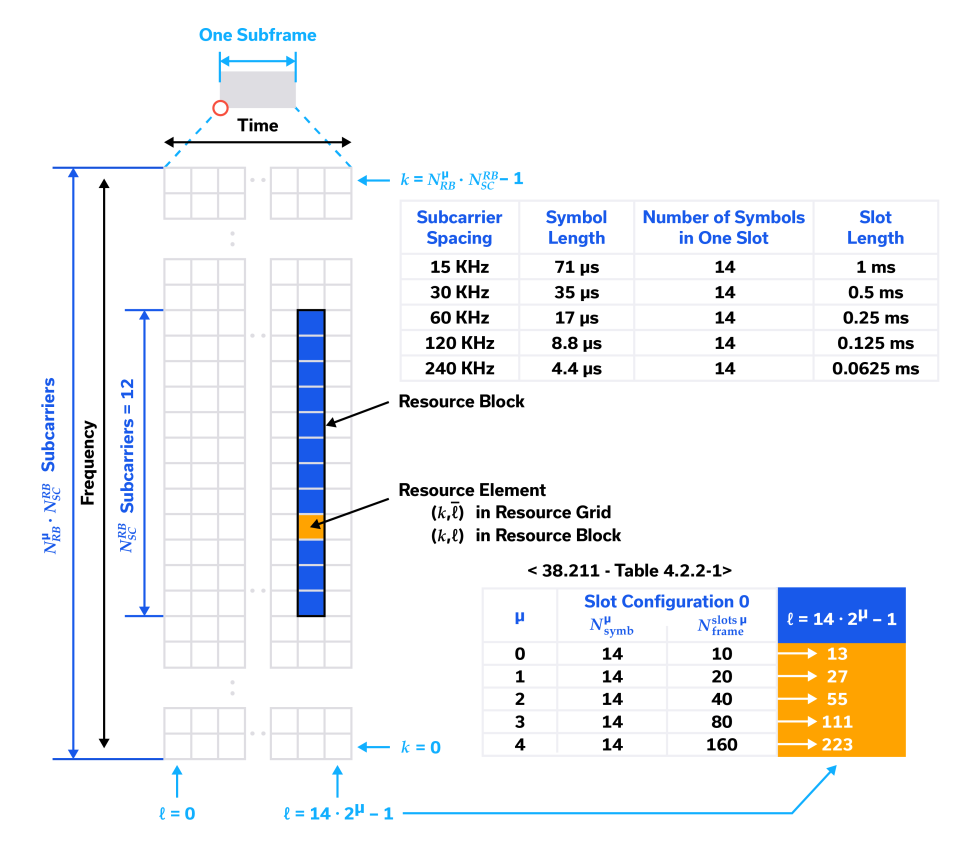
Additionally, LTE has a constant subcarrier spacing of 15 kHz, so that a Resource Block is always 180 kHz in the frequency domain. 5G NR includes flexibility in the subcarrier spacing, as shown in the table in the upper righthand portion of Figure 3. This flexibility in both the time and frequency domains enables 5G NR to take full advantage of the newer, higher frequency bands and broader bandwidths that have become available. 5G NR data transfer rates can often eclipse those of LTE by an order of magnitude.
Wi-Fi and OFDM – Achieving Significantly Higher Data Rates
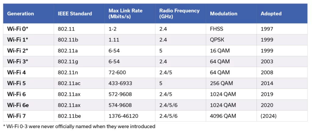
Wi-Fi is a good example of how OFDM with QAM modulation has yielded dramatic increases in data rates from generation to generation over time. Figure 4 shows just how exponential this growth in link rate has been. Since Wi-Fi access points often have many users, generation 6 of IEEE 802.11 and beyond (Wi-Fi 6 or newer) use OFDMA, or Orthogonal Frequency Division Multiple Access. OFDMA is a type of OFDM tailored for multiple users, as it allocates resources among multiple users in both the time and frequency domains. A quick glance at the last row in Figure 4 shows that the maximum predicted speed of a future Wi-Fi 7 link is upwards of a whopping 46 Gbits/s!
Conclusion
In this application note we discussed the basic characteristics of OFDM, first defining what is meant by orthogonal and why that matters. Next we showed how OFDM systems structure their transmissions in both the time and frequency domains and discussed how FFTs and IFFTs are utilized. A brief mention of the modulation of each of the subcarriers was followed by a description of how some of the more familiar applications such as 5G cellular and IEEE 802.11 Wi-Fi utilize OFDM. We concluded with a glimpse into the future of OFDM bandwidths and potential data rates for Wi-Fi specifically.
Related Products
References
- Weinstein, S. B. (November 2009). “The history of orthogonal frequency-division multiplexing”. IEEE Communications Magazine. IEEE Communications Magazine ( Volume: 47, Issue: 11, November 2009 ). 47 (11): 26–35. The history of orthogonal frequency-division multiplexing [History of Communications] | IEEE Journals & Magazine | IEEE Xplore
- Chang, R. W. (1966). “Synthesis of band-limited orthogonal signals for multi-channel data transmission”. Bell System Technical Journal. 45 (10): 1775–1796. Synthesis of band-limited orthogonal signals for multichannel data transmission | Nokia Bell Labs Journals & Magazine | IEEE Xplore
- Espacenet – search results, US Patent No. 3488445, Chang, Robert W., “Orthogonal frequency multiplex data transmission system”, published 1970-01-06, assigned to Bell Telephone Laboratories Inc.
- Orthogonal frequency-division multiplexing – Wikipedia
- What is orthogonal frequency-division multiplexing (OFDM)? (techtarget.com)
- LTE radio and Orthogonal Frequency Division Multiplexing (OFDM) (yatebts.com)
- Concepts of Orthogonal Frequency Division Multiplexing (OFDM) and 802.11 WLAN (keysight.com)
- 5G/LTE: OFDM Time and Frequency Domain | Tweet4Technology: LTE 5G-NR Wireless Technology Blogs
- 5G Frequency and Time Domain Structure – Our Technology Planet (ourtechplanet.com)
- Understanding the Wi-Fi® Variants


