The Basics of Orthogonal Frequency-Division Multiplexing (OFDM)

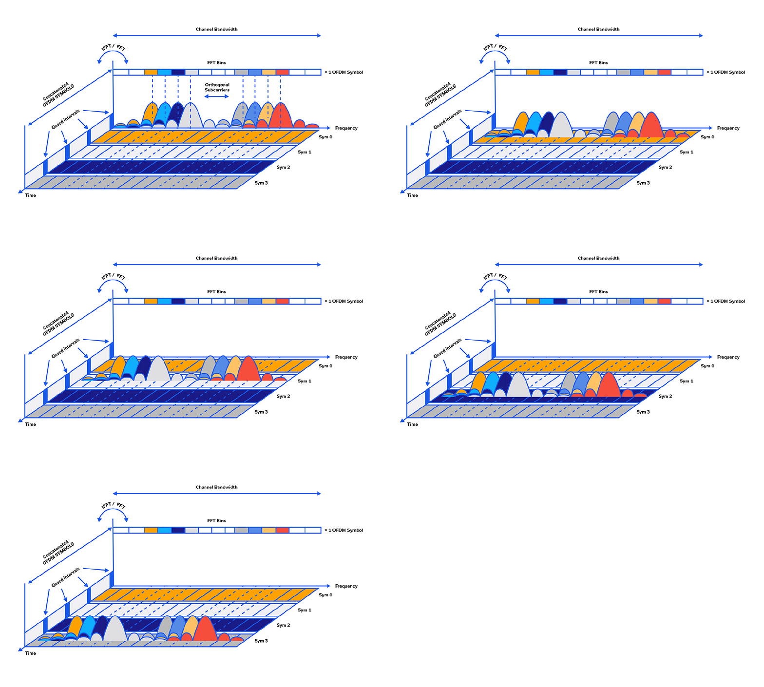
While traditional Frequency Division Multiplexing has been around for over 100 years, Orthogonal Frequency Division Multiplexing (OFDM) was first introduced by Robert W. Chang of Bell Laboratories in 1966.1,2,3,4 In OFDM, the stream of information is split between many closely-spaced, narrowband subcarriers instead of being relegated to a single wideband channel frequency.5 Single-channel modulation schemes tend to be sequential whereas, in OFDM, many bits can be sent in parallel, simultaneously, in the many subcarriers.5 So many bits can be packed onto the subcarriers simultaneously that the data rate of each subcarrier’s modulation can be much lower than that of a single-carrier architecture.
MMIC Technologies: Integrated Passive Devices (IPD)

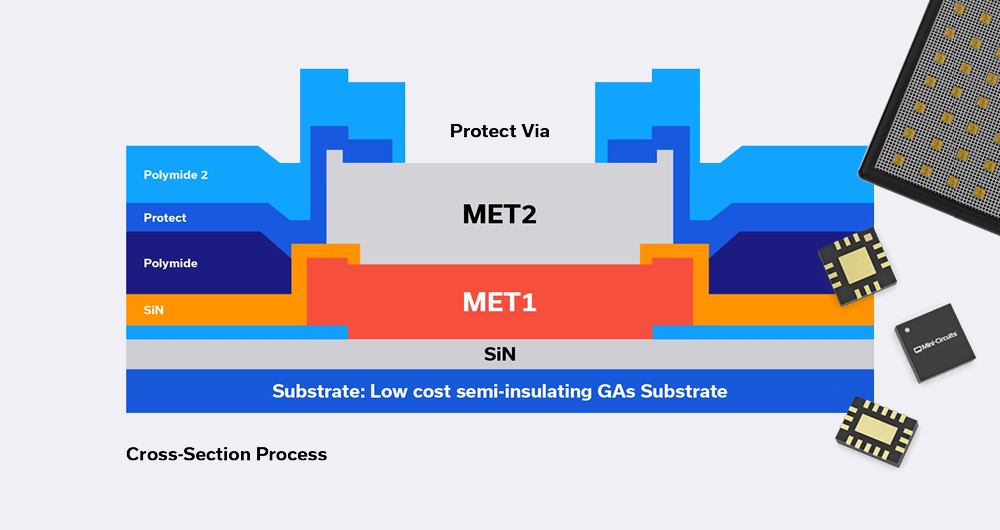
Monolithic Microwave Integrated Circuits (MMICs) with no active elements such as transistors, and containing only passive elements such as resistors, capacitors, inductors, are referred to as Integrated Passive Devices (IPD). These devices do not need DC power to operate, and do not perform frequency conversion as in the case of frequency mixers or frequency multipliers.
What’s the big deal about IPDs? The short answer is they perform vital functions which active elements cannot such as filtering, equalization, balanced-to-unbalanced line conversion (or vice versa) and many more as we will describe later.
פיזור המסתורין מעל שנאי ת”ר חלק 3: משמעות הפרמטרים של שנאי ת”ר

שני החלקים הראשונים של המאמר ‘פיזור המסתורין מעל שנאי ת”ר’ הציגו סקירה בסיסית של התיאוריה סביב שנאי ת”ר (RF) והיישומים שלהם וכן, העלו דיון עמוק יותר בעניין שנאי Balun לת”ר. חלק זה מספק הסבר לגבי פרמטרי הביצועים הבולטים יותר של שנאי ת”ר ותרשימי נתונים שמציגים את הדרך שבה קובעים את הפרמטרים האלו. הכרת הפרמטרים העיקריים האלו חיונית בעת בחירת שנאים עבור יישום, וכן כאשר עורכים השוואה בין דגמים שונים של שנאים.
פיזור המסתורין מעל שנאי ת”ר חלק 2: שנאי Balun ו- Unun

שנאי Balun ושנאי Unun מהווים חלקים חיוניים בשרשרות האותות בת”ר (RF) עבור יישומים רבים. תכנונים של שנאי Balun נקשרים בדרך כלל לשנאי ליבה וחוט, אם כי אפשר גם לממש אותם בטכנולוגיות של קווים קואקסיאליים וקווי Stripline עם צימוד. ההתנהגות של שנאי Balun ושנאי Unun הוצגה בחלק 1 של סדרה זו, כאשר קבענו ששני סוגי התקנים אלו מתוכננים למטרות של תיאום עכבות. ההבדל העיקרי בין השניים הוא בכך, ששנאי Balun מתוכננים כדי ליצור תיאום עכבות בין מעגלים מאוזנים למעגלים לא מאוזנים, בעוד ששנאי Unun מספקים תיאום עכבות בין שני מעגלים לא מאוזנים.
חלק 1 של הסדרה שלנו “פיזור המסתורין מעל שנאי ת”ר” דן בתיאוריה הבסיסית וביישומים של שנאי ת”ר. מאמר זה פונה לחקירה מעמיקה יותר של שנאי Balun ושנאי Unun, כשעיקר המוקד הוא בשנאי Balun בגלל השכיחות היותר גדולה שלהם ביישומים של העולם הממשי.
פיזור המסתורין מעל שנאי ת”ר חלק 1: דיון למתחילים על תיאוריה, טכנולוגיות ויישומים של שנאים

בעיקרו, שנאי אינו אלא שני נתיבים של מוליכים, או יותר, הקשורים ביניהם בשדה מגנטי משותף. כאשר שטף מגנטי משתנה מתפתח בתוך הליבה, כתוצאה מזרם חילופין שעובר דרך נתיב מוליך אחד, מושרה זרם בנתיב המוליך האחר. זרם מושרה זה יחסי ליחס של הצימוד המגנטי בין שני נתיבי ההולכה. היחס בין הצימוד המגנטי של הנתיבים המוליכים לבין הליבה קובע את המתח המושרה בנתיבי ההולכה הנוספים ומספק טרנספורמציה של העכבה (אימפדאנס) וגם העלאה או הורדה של המתח. אפשר להוסיף נתיבים מוליכים נוספים שכולם יכולים להיות עם יחסי צימוד שונים, על מנת לממש פונקציות שונות, וזו הסיבה ששנאי ת”ר (RF) הם התקנים כה מגוונים ורב-תכליתיים, אשר משמשים באופן נרחב בכל תעשיית הת”ר/ גלי המיקרו.
מימוש נפוץ של שנאי ת”ר מורכב משני חוטים נפרדים, או יותר, מלופפים סביב ליבה מגנטית (או ליבת אוויר במקרה של תדירויות גבוהות), וזו הסיבה ששנאי ת”ר מתוארים לא פעם בתור היחס בין מספר הליפופים או הכריכות.
Demystifying Transformers: Baluns and Ununs

Baluns and ununs are essential in RF signal chains for many applications. RF balun designs are most commonly associated with core-and-wire transformers, but can also be realized through coaxial and coupled stripline technologies. The behavior of baluns and ununs was introduced in Part 1 of this series, where we established that both these devices are designed for impedance matching purposes. The major difference between them is that baluns are designed to match impedances between balanced and unbalanced circuits, whereas ununs provide impedance matching between two unbalanced circuits.
Demystifying RF Transformers: A Primer on the Theory, Technologies and Applications – Part 1

In essence, a transformer is merely two or more conductive paths linked by a mutual magnetic field. When a varying magnetic flux is developed within the core by alternating current passing through one conductive path, a current is then induced in the other conductive paths. This induced current is proportional to the ratio of magnetic coupling between the two conductive paths. The ratio of the magnetic coupling of the conductive paths with the core determines the induced voltage in the additional conductive paths, providing both an impedance transformation and a voltage step-up or step-down. Additional conductive paths, potentially all with different coupling ratios, may be added to realize various functions, which is why RF transformers are such varied and versatile devices used widely throughout the RF/microwave industry.
ביטול השימוש ב-Bias Tee במוצא של מגברי Push–Pull באמצעות שימוש בשנאי 3:1 לא מאוזן למאוזן TCM3–452X+

מגברי Push-Pull (דחף-סחב) משמשים במערכות מרובות אוקטבות כדי לשפר את הספק המוצא והנצילות של המגבר, לדכא הרמוניות לא רצויות ולשפר את הטווח הדינמי של המערכת. בתכנון של מגבר Push-Pull אות המקור מסופק לשני טרנזיסטורים או מגברים מתואמים במקביל וביחס מופע (פאזה) של 180º. כאשר מחברים אותם מחדש בעזרת התקן מסכם שני בהזזת מופע של 180º, האותות הבסיסיים נמצאים במופע אחד ובסיכום של פעמיים ההספק של כל מחצית, שעה שההרמוניות מסדר זוגי הן במופע הפוך, וכך מתבטלים באופן אידיאלי האותות הבלתי רצויים האלו. במציאות, חוסר האיזון של המופע והמשרעת (אמפליטודה) של מעגלי הפיצול והסיכום גורם ל”קלקול” של הביטול האידיאלי. עם זאת, התוצאה הנקייה היא עדיין דיכוי משמעותי של ההרמוניות הזוגיות, בדרך כלל ב- 20 dB עד 40 dB.
Eliminating Bias Tees from Push-Pull Amplifier Outputs Using TCM3-452X+ 3:1 Unbalanced-to-Balanced Transformer

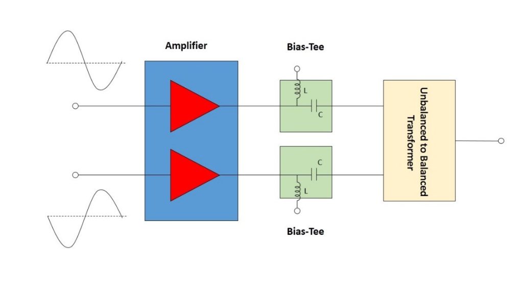
Push-pull amplifiers are used in many multi-octave systems to enhance amplifier output power and efficiency, suppress unwanted harmonics and improve system dynamic range. In a push-pull amplifier design, two matched transistors or amplifiers are supplied by the source signal in parallel and at a 180° phase relationship. When re-combined through a second 180° phase shifting combiner, the fundamental signals are in-phase and combined at twice the power of each half, while the even order harmonics are out-of-phase, creating ideal cancellation of these unwanted signals. In reality, the phase and amplitude unbalance of the splitting-combining circuits result in degradation of the ideal cancellation. However, the net result is still significant suppression of the even harmonics, typically by 20 to 40 dB.


