
MCDI offers a broad selection of Mini-Circuits RF and microwave Voltage Controlled Oscillators – VCOs for frequency generation, phase-locked loops, local oscillators, frequency synthesizers, radar, communications and RF test systems.
The portfolio includes narrowband and wideband VCOs, low-phase-noise oscillators, 5 V tuning models for PLL applications, dual-output VCOs, surface-mount, plug-in and coaxial configurations, with selected models covering frequencies from 35 MHz to 6.84 GHz.
Mini-Circuits VCOs are available with a wide range of tuning bandwidths, output-power levels, tuning sensitivities, phase-noise performance, control bandwidths and supply voltages.
Important VCO selection parameters include:
MCDI’s Application Engineering team in Israel can assist you in selecting the appropriate VCO according to your frequency plan, tuning requirements, phase-noise target, PLL architecture, output-power requirement and mechanical format.
Hebrew & English Professional Support
Get a quote within hours or less
DDP & Ex-Works - your choice
Custom Adapters & Catalog modifications
Access to Mini-Circuits full portfolio
Mini-Circuits Quality & Reliability
Use the VCO Catalog below to search and compare Mini-Circuits oscillators according to your application requirements.
For complete RF, phase-noise, tuning, temperature, harmonic, spurious, power-supply and absolute maximum specifications, always review the individual Mini-Circuits product datasheet.
Search according to:
Compare dedicated 5 V tuning VCO models according to:
Compare according to:
Search according to:
A Voltage Controlled Oscillator – VCO is an RF oscillator whose output frequency changes according to an applied control or tuning voltage.
The basic relationship can be represented as:
Output Frequency = f(VTUNE)
As the tuning voltage changes, the VCO moves through its specified frequency range.
For example, a VCO might tune from:
2.0 GHz to 3.0 GHz
as its tuning voltage changes through its specified control range.
VCOs are fundamental building blocks in:
A VCO can operate as a standalone tunable RF source or as part of a feedback-controlled system.
In a simple application, the tuning voltage directly determines the oscillator frequency.
In a phase-locked loop, a control system continuously adjusts the VCO tuning voltage so that its frequency and phase follow a stable reference.
This combination can provide:
Stable local oscillator generation
Surface-mount VCOs are designed for PCB-level integration into RF equipment.
Mini-Circuits offers VCOs ranging from narrowband and spot-frequency products to wideband models covering large tuning ranges.
Selected wideband devices cover up to approximately 1.5 octaves.
Surface-mount VCOs are useful in:
Important parameters include:
Phase noise is one of the most important VCO specifications in many RF systems.
Low-phase-noise VCOs are particularly valuable in:
Mini-Circuits VCO datasheets commonly specify phase noise at several offset frequencies from the carrier, such as:
The required phase-noise performance depends on the complete system architecture and the offset frequencies of greatest importance.
Mini-Circuits offers a dedicated family of 5 V tuning VCOs designed for convenient integration with PLL ICs and low-voltage control circuitry.
These VCOs typically use a tuning-voltage range up to approximately 5 V, depending on model.
They can simplify integration where the PLL loop-filter output cannot provide the higher tuning voltages required by conventional wideband VCOs.
Typical applications include:
When selecting a 5 V tuning VCO, consider not only frequency range but also:
A dual-output VCO provides two RF outputs from the same oscillator.
This can be useful when the generated signal must feed two different circuits without adding an external RF splitter.
Potential applications include:
Mini-Circuits dual-output VCOs provide a primary output together with an auxiliary RF output.
Always review the specified power levels and loading requirements for both outputs.
Connectorized or coaxial VCOs are convenient for:
Mini-Circuits’ ZX95-series includes rugged connectorized VCO designs using integrated unibody construction.
Coaxial products can be connected directly into an RF setup without requiring a dedicated PCB.
Mini-Circuits also offers plug-in VCOs for through-hole and legacy RF designs.
These products remain useful in:
Plug-in models should be presented separately from the surface-mount 5 V PLL category because the product families have different mechanical and tuning characteristics.
Not every application requires wide tuning.
A narrowband VCO can often provide better performance in parameters such as:
when the required tuning range is relatively small.
Spot-frequency and narrowband models are useful where only limited tuning or frequency correction is required.
Start with the minimum and maximum oscillator frequency required by the system.
The selected VCO must cover the complete operating range under the relevant:
Do not select a VCO based only on nominal or room-temperature tuning data if the application operates over a wide environmental range.
Mini-Circuits’ current VCO portfolio includes selected models covering applications from 35 MHz to 6.84 GHz.
The tuning voltage – VTUNE controls the output frequency.
Different VCO families may require tuning ranges such as:
The tuning-voltage range must be compatible with the control circuit or PLL loop filter.
Tuning sensitivity describes how much the output frequency changes for a given change in tuning voltage.
It is normally expressed in:
MHz/V
For example:
50 MHz/V
means a 1 V change in tuning voltage produces approximately a 50 MHz change in oscillator frequency at that point in the tuning range.
Tuning sensitivity is important because it affects:
Tuning sensitivity may vary across the VCO tuning range, so the minimum and maximum values should be considered where appropriate.
An ideal VCO would change frequency at a constant rate as tuning voltage changes.
In practice, the tuning curve is not perfectly linear.
Tuning linearity describes how closely the frequency-versus-voltage characteristic follows a straight line.
Good linearity can be useful in:
In a closed-loop PLL, linearity may be less critical than other parameters because the feedback system corrects frequency error, but tuning sensitivity variation still affects loop dynamics.
Phase noise describes short-term random variations in oscillator phase.
It is normally specified as single-sideband noise power relative to the carrier in:
dBc/Hz
at a defined offset frequency.
For example:
−120 dBc/Hz at 10 kHz offset
means the oscillator’s single-sideband noise density 10 kHz away from the carrier is 120 dB below the carrier in a 1 Hz measurement bandwidth.
More negative values represent lower phase noise.
A phase-noise number is incomplete unless the offset frequency is also stated.
For example:
−120 dBc/Hz @ 10 kHz
and:
−120 dBc/Hz @ 1 MHz
describe very different oscillator performance.
Mini-Circuits typically provides phase-noise data at several offsets, including:
The relevant offsets depend on the application.
When a VCO is used as the local oscillator for a mixer, excessive phase noise can reduce receiver or transmitter performance.
Potential effects include:
Low phase noise is therefore particularly important in high-performance frequency-conversion systems.
Frequency pushing describes how much the VCO output frequency changes when the DC supply voltage changes, while tuning voltage is held constant.
It is normally expressed in:
MHz/V
For example:
0.5 MHz/V pushing
means approximately 0.5 MHz of output-frequency variation for each 1 V change in supply voltage under the specified conditions.
Lower pushing generally means the oscillator is less sensitive to supply variation.
Good power-supply regulation and decoupling remain important even when a VCO has low pushing.
Frequency pulling describes output-frequency change caused by changes in the impedance presented to the VCO’s RF output.
Mini-Circuits commonly specifies pulling using a load with:
12 dB return loss at all phases
and reports the resulting frequency change in:
MHz peak-to-peak
Lower pulling means the oscillator is less sensitive to variations in output load impedance.
Pulling can be especially important when the VCO drives:
An RF buffer amplifier may sometimes help isolate the VCO from load variation.
The two terms describe different effects:
Pushing
Frequency change caused by supply-voltage variation.
Pulling
Frequency change caused by output-load impedance variation.
Both parameters can affect frequency stability and should be evaluated separately.
The VCO must provide sufficient RF power to drive the next component in the signal chain.
Possible loads include:
If additional RF power is required, an amplifier can be added after the VCO.
A practical oscillator generates energy not only at its fundamental frequency but also at harmonic frequencies.
These may include:
Harmonics are normally specified in dBc, relative to the desired carrier.
For example:
−25 dBc second harmonic
means the harmonic is 25 dB below the carrier.
Applications requiring high spectral purity may need additional filtering after the VCO.
Oscillator outputs may also contain unwanted signals that are not integer harmonics of the carrier.
These are commonly called spurious responses or non-harmonic spurs.
Spurious performance may be important in:
Always review the complete datasheet when spectral purity is critical.
The 3 dB control or modulation bandwidth indicates how rapidly the VCO frequency can respond to changes at the tuning port.
This parameter can influence:
The specification may be expressed in kHz or MHz depending on product family.
Do not compare numeric values from different tables without also checking the units.
The oscillator requires a stable DC supply.
Important parameters include:
Because supply variation can cause frequency pushing, clean DC power is particularly important in low-phase-noise applications.
A VCO is one of the primary components in a phase-locked loop.
A typical PLL contains:
Reference → Phase Detector / PFD → Loop Filter → VCO → Divider → Feedback
The phase detector compares the divided VCO output with a stable reference.
The resulting error signal is filtered and applied to the VCO tuning port.
The loop continually adjusts the VCO until the output is locked to the desired frequency relationship.
When choosing a VCO for a PLL, consider:
The VCO’s tuning sensitivity becomes part of the PLL loop gain and therefore influences loop stability and loop-filter design.
A VCO is an analog tunable oscillator whose output frequency is controlled directly by voltage.
A frequency synthesizer normally combines a VCO or oscillator with:
to provide accurate and repeatable frequency generation.
Choose a VCO When:
Choose a Frequency Synthesizer When:
VCOs are commonly used to generate the local oscillator – LO signal for RF mixers.
The LO requirements may include:
The mixer’s required LO drive level should be compared with the VCO’s available output power.
If necessary, an RF amplifier can be used between the VCO and mixer.
A VCO can also drive a frequency multiplier to generate higher-frequency signals.
For example:
3 GHz VCO → X2 Multiplier → 6 GHz Output
or:
2 GHz VCO → X3 Multiplier → 6 GHz Output
When using this architecture, remember that frequency multiplication also increases phase noise relative to the multiplied carrier.
The complete VCO, amplifier, multiplier and filter chain should therefore be evaluated together.
VCOs provide the tunable RF source controlled by the PLL feedback loop.
A VCO can be combined with a reference, divider and PLL circuitry to produce a programmable frequency source.
VCOs provide local oscillator signals for receiver frequency conversion.
Low phase noise can be particularly important where strong adjacent interferers are present.
A VCO can provide a tunable carrier or LO signal for transmitter up-conversion.
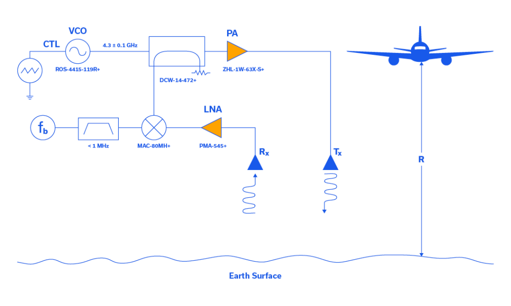
Radar systems may require:
depending on architecture.
VCOs are used in radio transceivers, frequency converters and PLLs across many wireless systems.
Low-phase-noise VCOs can support SATCOM local oscillator and frequency-generation functions.
Connectorized and surface-mount VCOs can be used in:
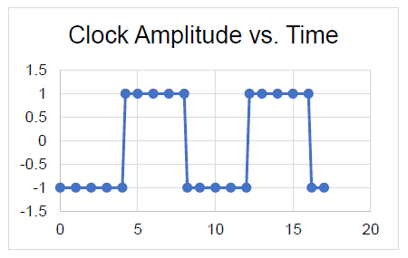
VCOs can also serve as tunable timing sources.
In clock applications, phase noise translates into timing jitter and can affect the performance of:
Phase-noise requirements should therefore be evaluated according to the relevant integration bandwidth and system jitter budget.
A Voltage Controlled Oscillator is an oscillator whose output frequency changes according to an applied tuning voltage.
The current Mini-Circuits VCO portfolio covers selected applications from approximately 35 MHz to 6.84 GHz, depending on model and product family.
Tuning voltage is the control voltage applied to the VCO’s tuning port to set its output frequency.
Different VCOs support different tuning-voltage ranges.
Tuning sensitivity describes how much oscillator frequency changes per volt of tuning-voltage change.
It is commonly expressed in MHz/V.
Phase noise describes short-term random variation in the oscillator’s phase and is normally specified in dBc/Hz at defined frequency offsets from the carrier.
More negative values generally indicate better phase-noise performance.
Phase noise changes according to distance from the carrier.
A phase-noise specification therefore has little meaning without an associated offset such as 1 kHz, 10 kHz, 100 kHz or 1 MHz.
Frequency pushing is the change in output frequency caused by a change in DC supply voltage while tuning voltage remains fixed.
It is commonly expressed in MHz/V.
Frequency pulling is the change in output frequency caused by changes in the impedance presented to the RF output.
Mini-Circuits commonly specifies it as peak-to-peak frequency variation for a defined load return loss.
Pushing is caused by changes in supply voltage.
Pulling is caused by changes in output load impedance.
A 5 V tuning VCO is designed so that its frequency can be controlled using a tuning-voltage range compatible with approximately 5 V PLL or control circuitry.
It can simplify integration with many PLL ICs.
A dual-output VCO provides two RF outputs generated by the same oscillator.
This can reduce the need for an external splitter when two circuits require access to the same oscillator signal.
The control or modulation bandwidth indicates how quickly the VCO can respond to changes at its tuning input.
It can be important in PLLs, modulation and fast-frequency-sweep applications.
Harmonics are unwanted oscillator outputs at integer multiples of the desired fundamental frequency.
They are typically specified in dBc relative to the main carrier.
A VCO is the tunable oscillator itself.
A frequency synthesizer typically combines an oscillator/VCO with reference, PLL, divider and control circuitry to produce an accurate programmed frequency source.
Yes.
VCOs are commonly used as local oscillator sources for RF mixers, provided their frequency range, output power, phase noise and spectral purity meet the mixer and system requirements.
Yes.
A VCO can feed an X2, X3 or other frequency multiplier to generate higher-frequency signals.
Phase-noise multiplication and harmonic filtering must be considered in the complete design.
Yes.
Phase noise in the frequency domain contributes to timing jitter in the time domain.
Clock applications therefore often require careful evaluation of phase noise across the relevant offset-frequency range.
Yes.
Mini-Circuits supports special and custom oscillator requirements.
MCDI can help define and submit VCO requirements for customers in Israel.
Yes.
MCDI’s Application Engineering team in Israel can help identify suitable Mini-Circuits VCOs according to frequency, tuning voltage, phase noise, output power, pushing, pulling, harmonic, PLL and mechanical requirements.
MCDI is Mini-Circuits’ exclusive representative and distributor in Israel, providing Israeli engineers and purchasing teams with access to Mini-Circuits RF products together with local technical, commercial and logistical support.
Local Application Engineering
Selecting a VCO requires balancing several interdependent specifications.
MCDI’s Application Engineers can help evaluate:
and identify suitable Mini-Circuits products.
Technical Support in Hebrew and English
Discuss your oscillator and frequency-generation requirements directly with an Israel-based engineering team familiar with Mini-Circuits RF components and complete signal chains.
PLL & Frequency-Generation Support
MCDI can assist with related Mini-Circuits products including:
allowing the VCO to be evaluated as part of the complete frequency-generation architecture.
Special & Custom Solutions
If a catalog VCO does not meet the required tuning range, phase noise, control voltage or package requirements, MCDI can assist with evaluating special or custom Mini-Circuits solutions.
Support from Selection Through Delivery
MCDI supports customers in Israel from product selection and quotation through ordering, logistics and post-sales technical assistance.




Before you leave, you should know that MCDI’s professional team of Application Engineers will be delighted to assist you in sourcing the right component. Just fill the form and we will be back to you shortly.