Flattening Negative Gain Slope with MMIC Fixed Equalizers

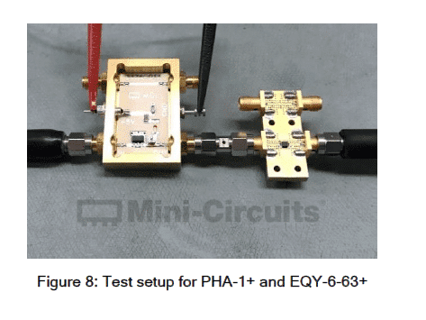
Equalizers are devices used to compensate for negative gain slope in the frequency response of a wide variety of RF systems. Unlike a standard attenuator with a flat frequency response, an equalizer is a unique kind of attenuator which exhibits lower insertion loss as frequency increases with some known slope. This is a useful characteristic for system designers working in wideband applications where the gain response of circuit elements or of the entire RF chain often varies across frequency.
More than Just a Phase: Understanding Phase Stability in RF Test Cables

One important factor in ensuring accurate, repeatable measurements in RF test applications is the stability of performance of the test cable used. In most test environments, cables undergo frequent bending during normal use, which can result in changes in phase and other performance parameters. Depending on the cable, these changes can be significant enough to degrade the accuracy and precision of your measurements. Therefore, in choosing the right test cable for your needs, it’s important to consider how bending affects cable phase performance and how a cable is (or isn’t) qualified for stability of phase versus flexure.
Compensating Frequency-Dependent Cable Loss in CATV Systems with Mini-Circuits Voltage-Variable Equalizers

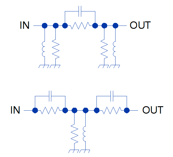
In broadband communications systems such as CATV equipment, system performance may critically rely on gain or attenuation flatness. In particular, CATV systems are often plagued by issues resulting from the frequency-dependent attenuation of very long cables (increasing with frequency) as well as the negative gain slope of certain amplifiers. This negative gain slope exhibited by CATV system components can cause a variety of headaches for system designers.
Affordable Solutions for Testing 28 GHz 5G Devices with Your 6 GHz Lab Instrumentation

The capabilities that define the 5G wireless standard will require utilization of wider bandwidths across more regions of spectrum than any current wireless technology. 5G communications will eventually occupy multiple bands from below 6 GHz to above 60 GHz. For now, much of the development effort is divided among sub-6 GHz bands for vehicular connectivity and longer-range transmissions, and the 26, 28, 38 and 60 GHz bands for enhanced mobile broadband applications. The migration to higher frequencies and the multi-band nature of the technology pose a variety of unique challenges for designers developing 5G devices and network equipment. Significant among these is the high cost of instrumentation for test and measurement over such a wide range of frequencies.
Minimizing Impedance Mismatches with Fixed Attenuators

Fixed attenuators are invaluable problem-solvers for circuit-level and system-level designers. In addition to controlling amplitude levels, fixed attenuators can improve the impedance match between impedance-sensitive devices such as amplifiers and filters, and provide the isolation needed to stabilize oscillators.
Model: ZYSWA-2-50DR+ (Redesigned Model)

Prior to developing our mechanical switch, Mini-Circuits purchased a significant quantity of mechanical switches for use in our production test facilities. These switches utilized a combination of springs and solenoids to accomplish the switching. Most operated for less than 1 million cycles, or approximately 50 days in our production environment. This turnover prompted Mini-Circuits to develop our own design to address the short operating life, long lead times, and high cost of using commercially available mechanical relay switches.
High-Order Switch Matrices Facilitate Network Infrastructure Testing

Testing cellular network infrastructure often requires measurement and data collection from dozens – even hundreds – of base stations (BTS) within a test environment. The volume and complexity of signal traffic in these multi-device, multi-user test systems necessitates commensurate capability for routing signals between base stations and test stations. By partnering with customers to lower costs and improve efficiency in high-volume test systems, Mini-Circuits has developed a line of high-order switch matrices supporting a wide variety of switching configurations and control methods. This article will present a case study of a 20 x 6 non-blocking, full access switch matrix used to facilitate signal routing in a cellular network test system with extensions for other applications.
Frequently Asked Questions About Power Detectors

Frequently Asked Questions About Power Detectors
Q. I recently purchased a PWR-6G power detector and was wondering if I need to have it calibrated, or if it came to me calibrated.
A. The PWR-6G+ is calibrated prior to shipping and therefore there is no need for calibration of new power detectors. A customer can start working once the power sensor software has loaded and the USB cable is plugged in to the computer. We recommend sending the PWR-6G+ once a year for calibration.
Ultra-Wideband, Low-Loss Couplers for Cable TV and Broadband Access Systems (DOCSIS® 3.1)

This article discusses the use of ultra-low loss, broadband distributed couplers in 75Ω systems such as broadband services over cable television networks (CATV).
Demystifying Pin-Outs: What Do We Mean by “Not Connected?”

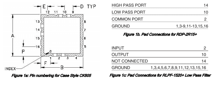
Mini-Circuits offers a wide range of products in miniature surface-mount (SMT) packages. Each package is identified by a case style number and defined by a case style drawing which clearly shows the outline dimensions, critical dimensions (if any), orientation, pin numbering, pin-out details, and material finish wherever applicable.
Some case styles are used in various Mini-Circuits products, and different signal pads may be used depending on the circuit design of each model. In some cases, some signal pads on the unit may be left unused and marked as “NOT CONNECTED” in the pin-out details on the datasheet.
This article explains by way of example what we mean when we denote signal pads this way, and how users may treat these pads when mounting the part on their board.


