Pairing Mixers with Reflectionless Filters to Improve System Performance
Introduction
Traditional filter designs employ circuits which reject undesired signals by reflecting them back to the source. There are many applications in which these reflections produce intermodulation products, gain ripples and other problems in system performance. Non-linear devices such as mixers respond to out-of-band frequencies and are highly sensitive to the reflections caused by conventional filter designs. This becomes especially challenging as filters are often needed near or adjacent to mixers to better define bandwidth or suppress unwanted harmonics.
While RF system designers have used several brute-force approaches to manage these adverse effects such as inserting attenuators or isolation amplifiers around sensitive components, these techniques are known to degrade overall system signal-to-noise ratio (SNR) and dynamic range. Absorption of stop band signals has been achieved by terminating one port of a diplexer (or all but one port of a multiplexer), but this approach is demanding on space requirements and still results in some reflections due to mismatch in the transition. Balanced filters with quadrature hybrids at the input and output can also be used to buffer the circuit from reflective elements, but the bandwidth of the filter is then limited by that of the hybrids used, which makes this technique unsuitable for broadband applications.
To support a clear and prevalent need to eliminate reflections from filters in the stop-band, Mini-Circuits has developed the patented X-series of reflectionless filters. These filters employ a novel filter topology in which undesired signals are fully absorbed and terminated internally and for which the reflection coefficient is zero for all frequencies.
Theory: Minimizing Reflections to Improve Dynamic Range
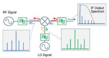
Reflectionless filters are particularly useful for pairing with sensitive non-linear devices where traditional filters are often problematic. A prime example is the case in which a filter is used at the output of a mixer in the signal chain. Mixers generate spurious mixing products, higher LO harmonics, and other unwanted signal elements that must be filtered out. However, with a conventional filter, these spurious tones are reflected back into the mixer where they can convert again, or re-mix with the desired signals to create a multitude of unintended signals that may fall within the desired pass-band.
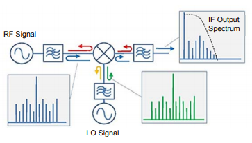
Figure 1: Typical intermodulation expansion due to reflections from multiple filters.
Reducing intermodulation products produced by the non-linear mixer has always been a design goal, and the industry has had various levels of success with high dynamic range FET based mixers. However, even the best mixers produce intermodulation products at some level from each port which then react with the neighboring elements in the RF chain. When these adjacent elements are filters, the out-of-band intermodulation products are fully reflected back into the mixer to re-combine with the fundamental signal and produce additional “family members” of unwanted spurious products. These spurious products make their way to the output IF, and several end up in-band, limiting the overall dynamic range of the system.
When out-of-band reflections from filters are minimized, those “family member” spurious products are reduced, resulting in a net reduction of in-band unwanted intermodulation products and improvement in overall system dynamic range.
Proof of Concept
An application circuit was assembled and tests were performed to compare system performance when a mixer was paired with a conventional filter to performance when the same mixer was paired with a reflectionless filter.
Test 1: IF Output Reflection Spectrum with Single Input Frequency
The test setup shown in Figure 3 was assembled and the reflection from the filter back to the output port of the mixer was measured in three cases for comparison:
Case 1: No filter at mixer output.
Case 2: Conventional filter at mixer output.
Case 3: Reflectionless filter at mixer output.
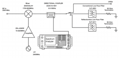
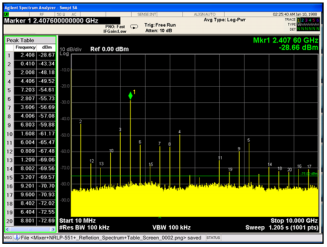
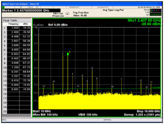
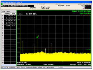
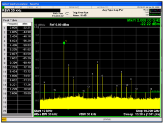
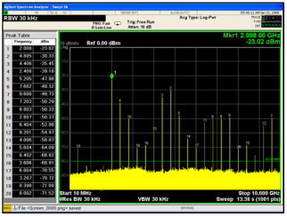
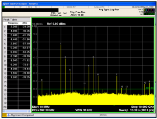
The test results for each case are shown in Figures 4 through 6. While the conventional filter reduces the reflections present when the mixer is used alone, the reflectionless filter virtually eliminates those reflections altogether. The reflected signal at 2 GHz exhibits a reduction of more than 30 dB from -34.35 dBm with the conventional filter to -66.12 dBm when the reflectionless filter is used. The other reflected signals were similarly suppressed when the reflectionless filter was used.
Test 2: IF Input Reflection Spectrum with Single Input Frequency
To measure the reflection through the mixer input back to the source, the test setup in Figure 7 was used. Again, three cases were tested:
Case 1: No filter at mixer output.
Case 2: Conventional filter at mixer output.
Case 3: Reflectionless filter at mixer output.
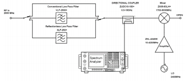
The difference in system performance when the reflectionless filter is used is less obvious in this test but still significant. While the nominal measurements of reflected signal before the mixer don’t show a significant reduction in the reflection strength, they do show greater consistency with the input reflection characteristics of the mixer when no filter is used. This means that effects generated by the reflectionless filter at the output add or subtract minimally to the natural reflections from the mixer input port. This essentially results in much more predictable behavior at the mixer input.
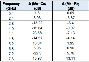
We can best see this difference by looking at the delta between measured reflections of the mixer alone and the measurements when each type of filter is used at the output. These delta values are shown in Table 1. Note the low variation when the reflectionless filter is used at the mixer output.

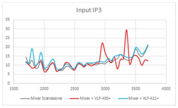
Test 3: Conversion Loss and IP3 Test (Sweeping RF and LO Frequencies)
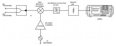
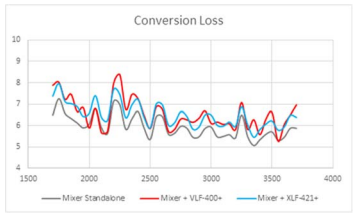
The test setup in Figure 11 was used to test the conversion loss and IP3. The RF1 signal was swept to test conversion loss. The RF2 signal was added to interfere with RF1 and test IP3. As in each of the previous tests, measurements were made for three cases:
Case 1: No filter at mixer output.
Case 2: Conventional filter at mixer output.
Case 3: Reflectionless filter at mixer output.
Conclusion
A comparison of system performance when a mixer is paired with a conventional filter versus a reflectionless filter shows that the reflectionless filter virtually eliminates reflections at the mixer output, dramatically improving system dynamic range. Additionally, more predictable reflection behavior is achieved at the mixer input, and conversion loss and IP3 conform closely to the performance of the mixer alone. These results suggest dramatic improvements in system performance can be achieved by pairing mixers with reflectionless filters in place of conventional filters.
Browse all RF reflectionless filters


