Mini-Circuits RF Power Splitters & Combiners from DC to 67 GHz with Local Engineering Support in Israel
MCDI offers a broad selection of Mini-Circuits RF, microwave and millimeter-wave power splitters, power dividers and power combiners for signal distribution, signal combining, RF test systems, communications, radar and high-power applications.
The standard Mini-Circuits catalog includes 2-way, 3-way, 4-way, 5-way, 6-way, 8-way, 10-way, 12-way, 16-way and up to 24-way configurations, with selected special and non-catalog higher-port-count solutions also available.
Products are available for both 50 Ω and 75 Ω systems, with:
Surface-mount
Connectorized
Plug-in
MMIC die
configurations.
Mini-Circuits splitter / combiner solutions cover frequencies from DC to 67 GHz, with connector interfaces including SMA, N-Type, BNC, F-Type, 2.92 mm, 2.4 mm, 1.85 mm and selected high-power 7/16 DIN configurations.
Available architectures include:
Core & Wire
LTCC
MMIC
Microstrip
Stripline
Resistive
High-power non-isolating combiners
MCDI’s Application Engineering team in Israel can assist you in selecting the appropriate splitter or combiner according to frequency range, number of ways, isolation, insertion loss, amplitude balance, phase balance, RF power, impedance, DC-pass requirements and mechanical interface.
2-way Connectorzied Power Splitter, 18000-26500MHz
Connectorzied
2
50
18,000.00
26500
29
0.70
1
0.03
11.00
DC Pass
Stripline
01/01/1970
ZC2PD-5R263-S+
2-way Connectorzied Power Splitter, 500-26500MHz
Connectorzied
2
50
500.00
26500
35
1.20
0
0.05
14.00
DC Pass
01/01/1970
ZC4PD-01263-S+
4-way Connectorzied Power Splitter, 1000-26500MHz
Connectorzied
4
50
1,000.00
26500
33
1.60
1
0.06
14.00
DC Pass
01/01/1970
ZC4PD-02263-S+
4-way Connectorzied Power Splitter, 2000-26500MHz
Connectorzied
4
50
2,000.00
26500
31
1.50
1
0.07
14.00
DC Pass
01/01/1970
ZC4PD-153-S+
4-way Connectorzied Power Splitter, 6000-15000MHz
Connectorzied
4
50
6,000.00
15000
22
1.30
8
0.40
10.00
DC Pass
01/01/1970
ZC4PD-18-S+
4-way Connectorzied Power Splitter, 1000-1800MHz
Connectorzied
4
50
1,000.00
1800
32
0.30
6
0.40
10.00
DC Pass
01/01/1970
ZC4PD-900-S+
4-way Connectorzied Power Splitter, 800-900MHz
Connectorzied
4
50
800.00
900
30
0.30
3
0.20
10.00
-
01/01/1970
ZC6PD-1900W-S+
6-way Connectorzied Power Splitter, 1500-2000MHz
Connectorzied
6
50
1,500.00
2000
30
0.50
0
0.60
10.00
DC Pass
01/01/1970
ZC8PD1-10-S+
8-way Connectorzied Power Splitter, 300-1000MHz
Connectorzied
8
50
300.00
1000
27
0.60
6
0.20
10.00
DC Pass
01/01/1970
ZCSC-3-R3+
3-way Connectorzied Power Splitter, 2-300MHz
Connectorzied
3
50
2.00
300
31
0.40
2
0.30
1.00
-
01/01/1970
ZCSC-8-1+
8-way Connectorzied Power Splitter, 2-250MHz
Connectorzied
8
50
2.00
250
30
0.80
4
0.30
1.00
-
01/01/1970
ZCSC-8-13-S+
8-way Connectorzied Power Splitter, 5-1000MHz
Connectorzied
8
50
5.00
1000
22
1.20
2
0.40
0.50
-
01/01/1970
ZCSC-8-152-S+
8-way Connectorzied Power Splitter, 0.5-1550MHz
Connectorzied
8
50
0.50
1550
38
2.50
4
0.30
0.50
-
Resistive
01/01/1970
ZESC-2-11+
2-way Connectorzied Power Splitter, 10-2000MHz
Connectorzied
2
50
10.00
2000
18
0.50
3
0.30
1.00
-
01/01/1970
ZF3RSC-542-S+
3-way Connectorzied Power Splitter, DC-5400MHz
Connectorzied
3
50
0.00
5400
19
1.60
10
0.50
0.10
-
Resistive
01/01/1970
ZFRSC-123+
2-way Connectorzied Power Splitter, DC-12000MHz
Connectorzied
2
50
0.00
12000
19
3.50
3
0.25
0.16
-
Resistive
01/01/1970
ZFRSC-183+
2-way Connectorzied Power Splitter, DC-18000MHz
Connectorzied
2
50
0.00
18000
6
0.70
7
0.50
0.16
-
Resistive
01/01/1970
ZFRSC-2050+
2-way Connectorzied Power Splitter, DC-2000MHz
Connectorzied
2
50
0.00
2000
6
0.30
2
0.20
0.75
-
Resistive
01/01/1970
ZFRSC-2075+
2-way Connectorzied Power Splitter, DC-2000MHz
Connectorzied
2
75
0.00
2000
6
0.30
2
0.20
0.75
-
Resistive
01/01/1970
ZFRSC-42+
2-way Connectorzied Power Splitter, DC-4200MHz
Connectorzied
2
50
0.00
4200
6
0.10
3
0.20
0.75
-
Resistive
01/01/1970
ZFRSC-4-842+
4-way Connectorzied Power Splitter, DC-8400MHz
Connectorzied
4
50
0.00
8400
6
0.30
4
0.30
0.16
-
Resistive
01/01/1970
ZFSC-10-1+
10-way Connectorzied Power Splitter, 0.5-100MHz
Connectorzied
10
50
0.50
100
30
0.40
6
0.30
1.00
-
01/01/1970
ZFSC-12-1+
12-way Connectorzied Power Splitter, 1-200MHz
Connectorzied
12
50
1.00
200
35
1.10
8
0.20
1.00
-
01/01/1970
ZFSC-12-11-S+
12-way Connectorzied Power Splitter, 10-300MHz
Connectorzied
12
50
10.00
300
33
1.10
4
0.30
1.00
-
01/01/1970
ZFSC-12-175+
12-way Connectorzied Power Splitter, 10-500MHz
Connectorzied
12
75
10.00
500
24
1.00
0
0.50
1.00
-
01/01/1970
ZFSC-16-12+
16-way Connectorzied Power Splitter, 0.1-200MHz
Connectorzied
16
50
0.10
200
27
0.70
6
0.20
1.00
-
01/01/1970
ZFSC-2-1+
2-way Connectorzied Power Splitter, 5-500MHz
Connectorzied
2
50
5.00
500
28
0.30
4
0.15
1.00
-
01/01/1970
ZFSC-2-10G+
2-way Connectorzied Power Splitter, 2000-10000MHz
Connectorzied
2
50
2,000.00
10000
20
0.60
12
0.50
1.00
DC Pass
01/01/1970
ZFSC-2-1-75+
2-way Connectorzied Power Splitter, 0.25-300MHz
Connectorzied
2
75
0.25
300
30
0.40
3
0.20
1.00
-
01/01/1970
ZFSC-2-1W+
2-way Connectorzied Power Splitter, 1-750MHz
Connectorzied
2
50
1.00
750
28
0.40
4
0.15
1.00
-
01/01/1970
ZFSC-2-1W-75+
2-way Connectorzied Power Splitter, 5-600MHz
Connectorzied
2
75
5.00
600
45
0.27
2
0.30
1.00
-
01/01/1970
ZFSC-2-2+
2-way Connectorzied Power Splitter, 10-1000MHz
Connectorzied
2
50
10.00
1000
25
0.50
4
0.15
1.00
-
01/01/1970
ZFSC-2-2500+
2-way Connectorzied Power Splitter, 10-2500MHz
Connectorzied
2
50
10.00
2500
17
0.60
4
0.30
1.00
-
01/01/1970
ZFSC-2-372+
2-way Connectorzied Power Splitter, 10-3700MHz
Connectorzied
2
50
10.00
3700
18
0.60
4
0.30
1.00
-
01/01/1970
ZFSC-2-4+
2-way Connectorzied Power Splitter, 0.2-1000MHz
Connectorzied
2
50
0.20
1000
25
0.50
4
0.15
1.00
-
01/01/1970
ZFSC-24-1-S
24-way Connectorzied Power Splitter, 0.2-100MHz
Connectorzied
24
50
0.20
100
25
1.00
0
0.40
1.00
-
01/01/1970
ZFSC-24-11
24-way Connectorzied Power Splitter, 1-200MHz
Connectorzied
24
50
1.00
200
22
1.00
0
0.80
1.00
-
01/01/1970
ZFSC-24-11-75
24-way Connectorzied Power Splitter, 1-200MHz
Connectorzied
24
75
1.00
200
33
0.80
0
0.40
1.00
-
01/01/1970
ZFSC-2-5+
2-way Connectorzied Power Splitter, 10-1500MHz
Connectorzied
2
50
10.00
1500
30
0.50
3
0.20
1.00
-
01/01/1970
ZFSC-2-6+
2-way Connectorzied Power Splitter, 0.002-60MHz
Connectorzied
2
50
0.00
60
30
0.30
3
0.20
1.00
-
01/01/1970
ZFSC-2-9G+
2-way Connectorzied Power Splitter, 3500-9000MHz
Connectorzied
2
50
3,500.00
9000
20
0.60
10
0.50
1.00
DC Pass
01/01/1970
ZFSC-3-1+
3-way Connectorzied Power Splitter, 1-500MHz
Connectorzied
3
50
1.00
500
30
0.50
3
0.30
1.00
-
01/01/1970
ZFSC-3-4+
3-way Connectorzied Power Splitter, 1-1000MHz
Connectorzied
3
50
1.00
1000
20
0.70
6
0.40
1.00
-
01/01/1970
ZFSC-3-4-75+
3-way Connectorzied Power Splitter, 1-1000MHz
Connectorzied
3
75
1.00
1000
27
0.40
6
0.70
1.00
-
01/01/1970
ZFSC-4-1+
4-way Connectorzied Power Splitter, 1-1000MHz
Connectorzied
4
50
1.00
1000
23
0.60
8
0.40
1.00
-
01/01/1970
ZFSC-4-175+
4-way Connectorzied Power Splitter, 10-1000MHz
Connectorzied
4
75
10.00
1000
38
0.60
0
0.30
1.00
-
01/01/1970
ZFSC-4-175W+
4-way Connectorzied Power Splitter, 5-1000MHz
Connectorzied
4
75
5.00
1000
36
0.50
3
0.20
1.00
-
01/01/1970
ZFSC-4-1W
4-way Connectorzied Power Splitter, 10-500MHz
Connectorzied
4
50
10.00
500
23
0.60
8
0.30
1.00
-
01/01/1970
ZFSC-4-1W+
4-way Connectorzied Power Splitter, 10-500MHz
Connectorzied
4
50
10.00
500
23
0.60
8
0.30
1.00
-
01/01/1970
ZFSC-4-3+
4-way Connectorzied Power Splitter, 10-300MHz
Connectorzied
4
50
10.00
300
38
0.60
6
0.10
1.00
-
01/01/1970
ZFSC-4375+
4-way Connectorzied Power Splitter, 50-90MHz
Connectorzied
4
75
50.00
90
34
0.30
6
0.15
1.00
-
01/01/1970
ZFSC-5-1+
5-way Connectorzied Power Splitter, 1-300MHz
Connectorzied
5
50
1.00
300
23
0.60
4
0.30
1.00
-
01/01/1970
ZFSC-6-1+
6-way Connectorzied Power Splitter, 1-175MHz
Connectorzied
6
50
1.00
175
26
0.75
6
0.40
1.00
-
01/01/1970
ZFSC-6-110
6-way Connectorzied Power Splitter, 1-500MHz
Connectorzied
6
50
1.00
500
26
0.60
6
0.30
1.00
-
01/01/1970
ZFSC-6-1-75+
6-way Connectorzied Power Splitter, 1-200MHz
Connectorzied
6
75
1.00
200
30
0.75
6
0.40
1.00
-
01/01/1970
ZFSC-8-1+
8-way Connectorzied Power Splitter, 0.5-175MHz
Connectorzied
8
50
0.50
175
30
0.80
2
0.20
1.00
-
01/01/1970
ZFSC-8375
8-way Connectorzied Power Splitter, 50-90MHz
Connectorzied
8
75
50.00
90
30
1.00
2
0.20
1.00
-
01/01/1970
ZFSC-8-4+
8-way Connectorzied Power Splitter, 5-700MHz
Connectorzied
8
50
5.00
700
25
1.20
5
0.40
1.00
-
01/01/1970
ZFSC-8-43+
8-way Connectorzied Power Splitter, 10-1000MHz
Connectorzied
8
50
10.00
1000
25
1.40
10
0.40
1.00
-
01/01/1970
ZMSC-2-1+
2-way Connectorzied Power Splitter, 0.1-400MHz
Connectorzied
2
50
0.10
400
25
0.40
3
0.20
1.00
-
01/01/1970
ZMSC-2-1W+
2-way Connectorzied Power Splitter, 1-650MHz
Connectorzied
2
50
1.00
650
35
0.50
3
0.20
1.00
-
01/01/1970
ZMSC-2-2
2-way Connectorzied Power Splitter, 0.002-60MHz
Connectorzied
2
50
0.00
60
30
0.30
3
0.25
1.00
-
01/01/1970
ZMSC-3-1+
3-way Connectorzied Power Splitter, 1-200MHz
Connectorzied
3
50
1.00
200
40
0.40
2
0.20
1.00
-
01/01/1970
ZMSC-4-1+
4-way Connectorzied Power Splitter, 0.1-200MHz
Connectorzied
4
50
0.10
200
30
0.50
6
0.20
1.00
-
01/01/1970
ZN12PD-17-S
12-way Connectorzied Power Splitter, 800-1700MHz
Connectorzied
12
50
800.00
1700
30
0.45
14
0.70
10.00
-
01/01/1970
ZN12PD-252-S+
12-way Connectorzied Power Splitter, 800-2450MHz
Connectorzied
12
50
800.00
2450
30
0.50
6
0.60
10.00
-
01/01/1970
ZN12PD-63SMP+
12-way Connectorzied Power Splitter, 600-6000MHz
Connectorzied
12
50
600.00
6000
19
3.00
8
0.80
20.00
DC Pass
01/01/1970
ZN2PD-02183-S+
2-way Connectorzied Power Splitter, 2000-18000MHz
Connectorzied
2
50
2,000.00
18000
20
0.50
4
0.30
10.00
DC Pass
01/01/1970
ZN2PD1-222-S+
2-way Connectorzied Power Splitter, 600-2200MHz
Connectorzied
2
50
600.00
2200
18
0.20
2
0.20
10.00
DC Pass
01/01/1970
ZN2PD-20-S+
2-way Connectorzied Power Splitter, 750-2000MHz
Connectorzied
2
50
750.00
2000
25
0.20
4
0.30
5.00
DC Pass
01/01/1970
ZN2PD2-14W-S+
2-way Connectorzied Power Splitter, 500-10500MHz
Connectorzied
2
50
500.00
10500
20
0.90
2
0.10
35.00
DC Pass
01/01/1970
ZN2PD2-50-S+
2-way Connectorzied Power Splitter, 500-5000MHz
Connectorzied
2
50
500.00
5000
25
0.80
4
0.50
10.00
DC Pass
01/01/1970
ZN2PD2-63-S+
2-way Connectorzied Power Splitter, 350-6000MHz
Connectorzied
2
50
350.00
6000
20
0.70
1
0.20
25.00
DC Pass
01/01/1970
ZN2PD2-63A+
2-way Connectorzied Power Splitter, 350-6000MHz
Connectorzied
2
50
350.00
6000
18
0.80
1
0.20
25.00
DC Pass
01/01/1970
ZN2PD-272SMP+
2-way Connectorzied Power Splitter, 600-2750MHz
Connectorzied
2
50
600.00
2750
22
0.40
1
0.10
10.00
DC Pass
01/01/1970
ZN2PD-622SMP+
2-way Connectorzied Power Splitter, 350-6200MHz
Connectorzied
2
50
350.00
6200
18
1.00
2
0.20
10.00
DC Pass
01/01/1970
ZN2PD-63-S+
2-way Connectorzied Power Splitter, 1800-6000MHz
Connectorzied
2
50
1,800.00
6000
24
0.40
4
0.30
10.00
DC Pass
01/01/1970
ZN2PD-920W-S+
2-way Connectorzied Power Splitter, 700-1050MHz
Connectorzied
2
50
700.00
1050
22
0.15
3
0.30
10.00
DC Pass
01/01/1970
ZN2PD-9G-S+
2-way Connectorzied Power Splitter, 1700-9000MHz
Connectorzied
2
50
1,700.00
9000
22
1.00
2
0.20
30.00
DC Pass
01/01/1970
ZN2PD-E653+
2-way Connectorzied Power Splitter, 10000-65000MHz
Connectorzied
2
50
10,000.00
65000
22
1.20
10
0.64
10.00
DC Pass
01/01/1970
ZN2PD-K44+
2-way Connectorzied Power Splitter, 10000-40000MHz
Connectorzied
2
50
10,000.00
40000
20
0.90
10
0.60
10.00
DC Pass
01/01/1970
ZN2PD-V54+
2-way Connectorzied Power Splitter, 10000-50000MHz
Connectorzied
2
50
10,000.00
50000
23
1.80
2
0.13
10.00
DC Pass
01/01/1970
ZN3PD-02183-S+
3-way Connectorzied Power Splitter, 2000-18000MHz
Connectorzied
3
50
2,000.00
18000
22
1.20
4
0.20
25.00
DC Pass
01/01/1970
ZN3PD-622W-S+
3-way Connectorzied Power Splitter, 1800-6200MHz
Connectorzied
3
50
1,800.00
6200
20
1.00
3
0.60
10.00
DC Pass
01/01/1970
ZN3PD-900-S
3-way Connectorzied Power Splitter, 800-900MHz
Connectorzied
3
50
800.00
900
30
0.20
0
0.50
10.00
DC Pass
01/01/1970
ZN3PD-900W-S
3-way Connectorzied Power Splitter, 650-1050MHz
Connectorzied
3
50
650.00
1050
22
0.30
0
0.80
10.00
DC Pass
01/01/1970
ZN4PD-02183-S+
4-way Connectorzied Power Splitter, 2000-18000MHz
Connectorzied
4
50
2,000.00
18000
20
1.00
3
0.30
30.00
DC Pass
01/01/1970
ZN4PD1-183W-S+
4-way Connectorzied Power Splitter, 4000-18000MHz
Connectorzied
4
50
4,000.00
18000
22
0.70
3
0.25
30.00
DC Pass
01/01/1970
ZN4PD1-63-S+
4-way Connectorzied Power Splitter, 2000-6000MHz
Connectorzied
4
50
2,000.00
6000
26
0.70
5
0.40
10.00
DC Pass
01/01/1970
ZN4PD1-63HP-S+
4-way Connectorzied Power Splitter, 250-6000MHz
Connectorzied
4
50
250.00
6000
23
1.00
2
0.20
30.00
DC Pass
01/01/1970
ZN4PD1-842-S+
4-way Connectorzied Power Splitter, 2100-8400MHz
Connectorzied
4
50
2,100.00
8400
19
1.30
5
0.50
10.00
DC Pass
01/01/1970
ZN4PD-20-S
4-way Connectorzied Power Splitter, 1800-2000MHz
Connectorzied
4
50
1,800.00
2000
31
0.30
4
0.50
10.00
DC Pass
01/01/1970
ZN4PD-272-S+
4-way Connectorzied Power Splitter, 500-2700MHz
Connectorzied
4
50
500.00
2700
22
0.90
3
0.25
10.00
DC Pass
01/01/1970
ZN4PD-642W-S+
4-way Connectorzied Power Splitter, 1600-6000MHz
Connectorzied
4
50
1,600.00
6000
23
0.90
4
0.20
10.00
DC Pass
01/01/1970
ZN4PD-920-S+
4-way Connectorzied Power Splitter, 800-920MHz
Connectorzied
4
50
800.00
920
30
0.25
2
0.20
10.00
DC Pass
01/01/1970
ZN4PD-K44+
4-way Connectorzied Power Splitter, 10000-40000MHz
Connectorzied
4
50
10,000.00
40000
22
1.50
6
0.30
20.00
-
01/01/1970
ZN6PD-02183-S+
6-way Connectorzied Power Splitter, 2000-18000MHz
Connectorzied
6
50
2,000.00
18000
22
1.40
6
0.40
25.00
-
01/01/1970
ZN6PD-63W-S+
6-way Connectorzied Power Splitter, 1800-6000MHz
Connectorzied
6
50
1,800.00
6000
20
1.00
7
0.90
10.00
DC Pass
01/01/1970
ZN8PD-02183-S+
8-way Connectorzied Power Splitter, 2000-18000MHz
Connectorzied
8
50
2,000.00
18000
20
1.40
5
0.30
20.00
DC Pass
01/01/1970
ZN8PD-113-S+
8-way Connectorzied Power Splitter, 2000-11000MHz
Connectorzied
8
50
2,000.00
11000
22
1.30
6
0.40
10.00
DC Pass
01/01/1970
ZN8PD1-53-S+
8-way Connectorzied Power Splitter, 500-5000MHz
Connectorzied
8
50
500.00
5000
20
1.50
14
0.50
10.00
DC Pass
01/01/1970
ZN8PD1-63W-S+
8-way Connectorzied Power Splitter, 500-6000MHz
Connectorzied
8
50
500.00
6000
24
1.50
4
0.30
10.00
DC Pass
01/01/1970
ZN8PD-272SMP+
8-way Connectorzied Power Splitter, 690-2750MHz
Connectorzied
8
50
690.00
2750
28
0.80
2
0.10
10.00
DC Pass
01/01/1970
ZN8PD-362HP+
8-way Connectorzied Power Splitter, 600-3600MHz
Connectorzied
8
50
600.00
3600
23
1.00
4
0.20
100.00
DC Pass
01/01/1970
ZN8PD-642W-S+
8-way Connectorzied Power Splitter, 1800-6400MHz
Connectorzied
8
50
1,800.00
6400
25
1.50
5
0.20
10.00
-
01/01/1970
ZN8PD-K44+
8-way Connectorzied Power Splitter, 10000-40000MHz
Connectorzied
8
50
10,000.00
40000
20
2.00
8
0.30
20.00
-
01/01/1970
ZSC-2-1+
2-way Connectorzied Power Splitter, 0.1-400MHz
Connectorzied
2
50
0.10
400
25
0.40
3
0.20
1.00
-
01/01/1970
ZSC-2-1-75+
2-way Connectorzied Power Splitter, 0.25-300MHz
Connectorzied
2
75
0.25
300
30
0.40
3
0.20
1.00
-
01/01/1970
ZSC-2-1W+
2-way Connectorzied Power Splitter, 1-650MHz
Connectorzied
2
50
1.00
650
35
0.50
3
0.20
1.00
-
01/01/1970
ZSC-2-2+
2-way Connectorzied Power Splitter, 0.002-60MHz
Connectorzied
2
50
0.00
60
30
0.30
3
0.25
1.00
-
01/01/1970
ZSC-2-2-75+
2-way Connectorzied Power Splitter, 0.002-60MHz
Connectorzied
2
75
0.00
60
30
0.30
3
0.25
1.00
-
01/01/1970
ZSC-2375+
2-way Connectorzied Power Splitter, 55-85MHz
Connectorzied
2
75
55.00
85
35
0.30
1
0.10
1.00
-
01/01/1970
ZSC-2-4
2-way Connectorzied Power Splitter, 10-1000MHz
Connectorzied
2
50
10.00
1000
35
0.50
4
0.20
1.00
-
01/01/1970
ZSC-2-4+
2-way Connectorzied Power Splitter, 10-1000MHz
Connectorzied
2
50
10.00
1000
35
0.50
4
0.20
1.00
-
01/01/1970
ZSC-3-1+
3-way Connectorzied Power Splitter, 1-200MHz
Connectorzied
3
50
1.00
200
40
0.40
2
0.20
1.00
-
01/01/1970
ZSC-3-1-75+
3-way Connectorzied Power Splitter, 1-200MHz
Connectorzied
3
75
1.00
200
35
0.40
3
0.20
1.00
-
01/01/1970
ZSC-3-2+
3-way Connectorzied Power Splitter, 0.01-30MHz
Connectorzied
3
50
0.01
30
40
0.15
2
0.30
1.00
-
01/01/1970
ZSC-4-1+
4-way Connectorzied Power Splitter, 0.1-200MHz
Connectorzied
4
50
0.10
200
30
0.50
6
0.20
1.00
-
01/01/1970
ZSC-4-3+
4-way Connectorzied Power Splitter, 0.25-250MHz
Connectorzied
4
50
0.25
250
30
0.50
6
0.20
1.00
-
01/01/1970
ZX10-2-12-S+
2-way Connectorzied Power Splitter, 2-1200MHz
Connectorzied
2
50
2.00
1200
21
0.50
3
0.50
0.50
-
01/01/1970
ZX10-2-1252-S+
2-way Connectorzied Power Splitter, 1800-12500MHz
Connectorzied
2
50
1,800.00
12500
20
1.10
12
0.90
1.85
DC Pass
01/01/1970
ZX10-2-126-S+
2-way Connectorzied Power Splitter, 7400-12600MHz
Connectorzied
2
50
7,400.00
12600
23
0.30
10
0.50
1.00
DC Pass
01/01/1970
ZX10-2-143M-S+
2-way Connectorzied Power Splitter, 4000-14000MHz
Connectorzied
2
50
4,000.00
14000
20
1.10
6
0.50
2.50
DC Pass
01/01/1970
ZX10-2-183-S+
2-way Connectorzied Power Splitter, 1500-18000MHz
Connectorzied
2
50
1,500.00
18000
20
1.00
4
0.20
30.00
DC Pass
01/01/1970
ZX10-2-20-S+
2-way Connectorzied Power Splitter, 200-2000MHz
Connectorzied
2
50
200.00
2000
20
0.80
6
0.40
0.50
-
01/01/1970
ZX10-2-222-S+
2-way Connectorzied Power Splitter, 800-2200MHz
Connectorzied
2
50
800.00
2200
24
0.80
4
0.20
1.50
-
01/01/1970
ZX10-2-25-S+
2-way Connectorzied Power Splitter, 1000-2500MHz
Connectorzied
2
50
1,000.00
2500
20
1.20
10
1.20
1.00
-
01/01/1970
ZX10-2-252-S+
2-way Connectorzied Power Splitter, 500-2500MHz
Connectorzied
2
50
500.00
2500
22
0.90
4
0.20
1.50
-
01/01/1970
ZX10-2-332-S+
2-way Connectorzied Power Splitter, 1600-3300MHz
Connectorzied
2
50
1,600.00
3300
24
0.80
5
0.20
1.50
-
01/01/1970
ZX10-2-42-S+
2-way Connectorzied Power Splitter, 1900-4200MHz
Connectorzied
2
50
1,900.00
4200
23
0.20
3
0.30
1.00
DC Pass
01/01/1970
ZX10-2-442-S+
2-way Connectorzied Power Splitter, 1500-4400MHz
Connectorzied
2
50
1,500.00
4400
20
1.00
6
0.30
1.50
-
01/01/1970
ZX10-2-622-S+
2-way Connectorzied Power Splitter, 2900-6200MHz
Connectorzied
2
50
2,900.00
6200
24
0.90
9
0.30
1.50
-
01/01/1970
ZX10-2-71-S+
2-way Connectorzied Power Splitter, 2950-7100MHz
Connectorzied
2
50
2,950.00
7100
23
0.25
3
0.40
1.00
DC Pass
01/01/1970
ZX10-2-852-S+
2-way Connectorzied Power Splitter, 500-8500MHz
Connectorzied
2
50
500.00
8500
20
1.90
8
0.90
2.50
DC Pass
01/01/1970
ZX10-2-98-S+
2-way Connectorzied Power Splitter, 4750-9800MHz
Connectorzied
2
50
4,750.00
9800
23
0.30
9
0.50
1.00
DC Pass
01/01/1970
ZX10-4-14-S+
4-way Connectorzied Power Splitter, 1100-1450MHz
Connectorzied
4
50
1,100.00
1450
20
0.80
7
0.80
2.50
-
01/01/1970
ZX10-4-19-S+
4-way Connectorzied Power Splitter, 1425-1900MHz
Connectorzied
4
50
1,425.00
1900
20
0.75
6
0.90
2.50
-
01/01/1970
ZX10-4-24-S+
4-way Connectorzied Power Splitter, 1675-2350MHz
Connectorzied
4
50
1,675.00
2350
20
0.90
5
0.70
2.50
-
01/01/1970
ZX10-4-27-S+
4-way Connectorzied Power Splitter, 2225-2700MHz
Connectorzied
4
50
2,225.00
2700
20
1.00
9
1.20
2.50
-
01/01/1970
ZX10-4A-11-S+
4-way Connectorzied Power Splitter, 800-1125MHz
Connectorzied
4
50
800.00
1125
22
0.60
4
0.60
2.50
-
01/01/1970
ZX10-4A-14-S+
4-way Connectorzied Power Splitter, 1100-1450MHz
Connectorzied
4
50
1,100.00
1450
25
0.60
4
0.70
2.50
-
01/01/1970
ZX10-4A-19-S+
4-way Connectorzied Power Splitter, 1425-1900MHz
Connectorzied
4
50
1,425.00
1900
22
0.75
4
0.70
2.50
-
01/01/1970
ZX10-4A-24-S+
4-way Connectorzied Power Splitter, 1675-2200MHz
Connectorzied
4
50
1,675.00
2200
23
0.80
6
0.60
2.50
-
01/01/1970
ZX10R-14-S+
2-way Connectorzied Power Splitter, DC-10000MHz
Connectorzied
2
50
0.00
10000
6
0.50
3
0.20
0.16
-
Resistive
01/01/1970
NP2G+
2-way SMT Power Splitter, 1150-1950MHz
SMT
2
50
1,150.00
1950
13
0.40
0
0.10
1.50
MMIC
01/01/1970
ZC16PD-2185-S+
16-way Connectorzied Power Splitter, 1800-2600MHz
Connectorzied
16
50
1,800.00
2600
30
0.50
6
0.70
10.00
-
01/01/1970
EP2KA+
2-way SMT Power Splitter, 10000-43500MHz
SMT
2
50
10,000.00
43500
17
2.20
9
0.57
1.25
DC Pass
MMIC
01/01/1970
ZN2PD1-63+
2-way Connectorzied Power Splitter, 500-6000MHz
Connectorzied
2
50
500.00
6000
18
0.45
1
0.10
30.00
DC Pass
01/01/1970
ZC4PD-K0244+
4-way Connectorzied Power Splitter, 2000-40000MHz
Connectorzied
4
50
2,000.00
40000
28
2.70
2
0.14
20.00
DC Pass
01/01/1970
ZC8PD-06263-S+
8-way Connectorzied Power Splitter, 6000-26500MHz
Connectorzied
8
50
6,000.00
26500
28
1.20
2
0.11
20.00
DC Pass
Stripline
01/01/1970
ZC2PD-K0144+
2-way Connectorzied Power Splitter, 1000-40000MHz
Connectorzied
2
50
1,000.00
40000
36
0.90
1
0.05
20.00
DC Pass
01/01/1970
ZC2PD-K0244+
2-way Connectorzied Power Splitter, 2000-40000MHz
Connectorzied
2
50
2,000.00
40000
32
0.80
0
0.04
20.00
DC Pass
01/01/1970
ZC2PD-K0644+
2-way Connectorzied Power Splitter, 6000-40000MHz
Connectorzied
2
50
6,000.00
40000
29
0.70
1
0.03
20.00
DC Pass
Stripline
01/01/1970
ZC2PD-K5R44W+
2-way Connectorzied Power Splitter, 500-40000MHz
Connectorzied
2
50
500.00
40000
35
1.90
1
0.10
20.00
DC Pass
01/01/1970
ZN4PD1-63LW-S+
4-way Connectorzied Power Splitter, 500-6000MHz
Connectorzied
4
50
500.00
6000
23
0.60
2
0.15
30.00
DC Pass
01/01/1970
ZN6PD1-63-S+
6-way Connectorzied Power Splitter, 600-6000MHz
Connectorzied
6
50
600.00
6000
20
2.50
10
0.80
20.00
DC Pass
01/01/1970
ZN12PD-63-S+
12-way Connectorzied Power Splitter, 600-6000MHz
Connectorzied
12
50
600.00
6000
18
3.00
10
0.90
20.00
DC Pass
01/01/1970
ZC2PD-K1844+
2-way Connectorzied Power Splitter, 18000-40000MHz
Connectorzied
2
50
18,000.00
40000
27
0.80
1
0.05
20.00
DC Pass
01/01/1970
ZC4PD-K1844+
4-way Connectorzied Power Splitter, 18000-40000MHz
Connectorzied
4
50
18,000.00
40000
27
1.20
3
0.12
20.00
DC Pass
01/01/1970
ZC3PD-18263-S+
3-way Connectorzied Power Splitter, 18000-26500MHz
Connectorzied
3
50
18,000.00
26500
35
0.90
2
0.17
20.00
DC Pass
Stripline
01/01/1970
ZC4PD-18263-S+
4-way Connectorzied Power Splitter, 18000-26500MHz
Connectorzied
4
50
18,000.00
26500
28
1.10
2
0.10
20.00
DC Pass
Stripline
01/01/1970
ZC4PD-06263-S+
4-way Connectorzied Power Splitter, 6000-26500MHz
Connectorzied
4
50
6,000.00
26500
26
1.50
2
0.13
20.00
DC Pass
Stripline
01/01/1970
ZC4PD-K0644+
4-way Connectorzied Power Splitter, 6000-40000MHz
Connectorzied
4
50
6,000.00
40000
26
1.50
2
0.13
20.00
DC Pass
Stripline
01/01/1970
ZC6PD-K1844+
6-way Connectorzied Power Splitter, 18000-40000MHz
Connectorzied
6
50
18,000.00
40000
25
1.60
6
0.35
20.00
DC Pass
Stripline
01/01/1970
ZC6PD-18263-S+
6-way Connectorzied Power Splitter, 18000-26500MHz
Connectorzied
6
50
18,000.00
26500
24
1.10
5
0.28
20.00
DC Pass
Stripline
01/01/1970
ZC4PD-5R263-S+
4-way Connectorzied Power Splitter, 500-26500MHz
Connectorzied
4
50
500.00
26500
34
2.70
1
0.15
20.00
DC Pass
Stripline
01/01/1970
ZC4PD-K5R44W+
4-way Connectorzied Power Splitter, 500-40000MHz
Connectorzied
4
50
500.00
40000
36
2.70
2
0.10
20.00
DC Pass
Stripline
01/01/1970
SCG-2-242+
2-way SMT Power Splitter, 1000-2400MHz
SMT
2
50
1,000.00
2400
15
0.80
1
0.10
2.00
-
LTCC
01/01/1970
SCG-2-322+
2-way SMT Power Splitter, 1800-3200MHz
SMT
2
50
1,800.00
3200
15
0.70
1
0.10
2.00
-
LTCC
01/01/1970
SCG-2-592+
2-way SMT Power Splitter, 3800-5900MHz
SMT
2
50
3,800.00
5900
15
0.80
1
0.10
2.00
-
LTCC
01/01/1970
ZB4PD-6.4-S+
4-way Connectorzied Power Splitter, 5400-6800MHz
Connectorzied
4
50
5,400.00
6800
25
0.60
9
0.90
10.00
DC Pass
01/01/1970
SCG-3-162+
3-way SMT Power Splitter, 900-1600MHz
SMT
3
50
900.00
1600
18
1.20
5
0.20
2.00
-
LTCC
01/01/1970
SCG-3-262+
3-way SMT Power Splitter, 1600-2600MHz
SMT
3
50
1,600.00
2600
17
1.20
5
0.40
2.00
-
LTCC
01/01/1970
SCG-3-592+
3-way SMT Power Splitter, 4400-5900MHz
SMT
3
50
4,400.00
5900
17
1.20
5
0.40
2.00
-
LTCC
01/01/1970
ZC4PD-K0144+
4-way Connectorzied Power Splitter, 1000-40000MHz
Connectorzied
4
50
1,000.00
40000
33
1.80
1
0.10
20.00
DC Pass
Stripline
01/01/1970
ZC3PD-K1844+
3-way Connectorzied Power Splitter, 18000-40000MHz
Connectorzied
3
50
18,000.00
40000
31
1.20
3
0.15
13.60
DC Pass
01/01/1970
ZC8PD-K5R44W+
8-way Connectorzied Power Splitter, 500-40000MHz
Connectorzied
8
50
500.00
40000
35
4.10
1
0.18
20.00
DC Pass
Stripline
01/01/1970
ZC8PD-5R263-S+
8-way Connectorzied Power Splitter, 500-26500MHz
Connectorzied
8
50
500.00
26500
35
4.10
3
0.20
20.00
DC Pass
Stripline
01/01/1970
ZC8PD-18263-S+
8-way Connectorzied Power Splitter, 18000-26500MHz
Connectorzied
8
50
18,000.00
26500
26
1.70
4
0.19
20.00
DC Pass
Stripline
01/01/1970
ZC8PD-01263-S+
8-way Connectorzied Power Splitter, 1000-26500MHz
Connectorzied
8
50
1,000.00
26500
26
3.20
2
0.14
20.00
DC Pass
Stripline
01/01/1970
ZC8PD-02263-S+
8-way Connectorzied Power Splitter, 2000-26500MHz
Connectorzied
8
50
2,000.00
26500
31
2.10
2
0.11
20.00
DC Pass
Stripline
01/01/1970
ZC8PD-K0644+
8-way Connectorzied Power Splitter, 6000-40000MHz
Connectorzied
8
50
6,000.00
40000
28
2.00
2
0.12
20.00
DC Pass
Stripline
01/01/1970
ZC8PD-K1844+
8-way Connectorzied Power Splitter, 18000-40000MHz
Connectorzied
8
50
18,000.00
40000
26
1.80
5
0.16
20.00
DC Pass
Stripline
01/01/1970
ZC16PD-K0644+
16-way Connectorzied Power Splitter, 6000-40000MHz
Connectorzied
16
50
6,000.00
40000
26
2.20
6
0.28
20.00
DC Pass
Stripline
01/01/1970
ZC16PD-K1844+
16-way Connectorzied Power Splitter, 18000-40000MHz
Connectorzied
16
50
18,000.00
40000
22
3.10
5
0.20
20.00
DC Pass
Stripline
01/01/1970
ZC16PD-06263-S+
16-way Connectorzied Power Splitter, 6000-26500MHz
Connectorzied
16
50
6,000.00
26500
24
2.20
3
0.20
20.00
DC Pass
Stripline
01/01/1970
ZC16PD-18263-S+
16-way Connectorzied Power Splitter, 18000-26500MHz
Connectorzied
16
50
18,000.00
26500
23
3.10
3
0.24
20.00
DC Pass
Stripline
01/01/1970
ZN2PD-183W-S+
2-way Connectorzied Power Splitter, 500-18000MHz
Connectorzied
2
50
500.00
18000
24
0.80
1
0.05
20.00
DC Pass
Stripline
01/01/1970
WP4P1-D+
4-way Power Splitter Die, 1525-2375 MHz
DIE
4
50
1,525.00
2375
26
0.90
2
0.20
1.50
MMIC
01/01/1970
WP4R-D+
4-way Power Splitter Die, 2000-3000 MHz
DIE
4
50
2,000.00
3000
24
0.70
2
0.10
1.50
MMIC
01/01/1970
ZN2PD-83W-N+
2-way Connectorzied Power Splitter, 500-8000MHz
Connectorzied
2
50
500.00
8000
24
0.50
1
0.04
20.00
DC Pass
Stripline
01/01/1970
EP2RCW+
2-way SMT Power Splitter, DC-8000MHz
SMT
2
50
0.00
8000
23
4.80
0
0.02
0.30
-
Resistive , MMIC
01/01/1970
EP2RKU+
2-way SMT Power Splitter, DC-18000MHz
SMT
2
50
0.00
18000
26
3.30
1
0.02
0.30
-
Resistive , MMIC
01/01/1970
ZN4PD-5R183-S+
4-way Connectorzied Power Splitter, 500-18000MHz
Connectorzied
4
50
500.00
18000
25
1.20
3
0.10
20.00
DC Pass
Stripline
01/01/1970
EP4RKU+
4-way SMT Power Splitter, DC-18000MHz
SMT
4
50
0.00
18000
18
3.80
1
0.20
0.60
-
Resistive , MMIC
01/01/1970
EP4KA+
4-way SMT Power Splitter, 10700-31000MHz
SMT
4
50
10,700.00
31000
19
0.60
4
0.20
0.60
DC Pass
MMIC
01/01/1970
EP2RCW-D+
2-way Power Splitter Die, DC-8000MHz
DIE
2
50
0.00
8000
22
4.50
0
0.10
0.60
-
Resistive , MMIC
01/01/1970
EP2RKU-D+
2-way Power Splitter Die, DC-18000MHz
DIE
2
50
0.00
18000
23
2.90
0
0.10
0.60
-
Resistive , MMIC
01/01/1970
EP4RKU-D+
4-way Power Splitter Die, DC-18000MHz
DIE
4
50
0.00
18000
23
4.80
0
0.20
0.60
-
Resistive , MMIC
01/01/1970
EP4KA-D+
4-way Power Splitter Die, 10700-31000 MHz
DIE
4
50
10,700.00
31000
18
3.80
1
0.20
0.60
DC Pass
MMIC
01/01/1970
ZC2PD-V154+
2-way Connectorzied Power Splitter, 1000-50000MHz
Connectorzied
2
50
1,000.00
50000
32
1.90
1
0.11
16.00
DC Pass
Stripline
01/01/1970
ZC2PD-V254+
2-way Connectorzied Power Splitter, 2000-50000MHz
Connectorzied
2
50
2,000.00
50000
28
1.00
1
0.09
16.00
DC Pass
Stripline
01/01/1970
ZC2PD-E1653+
2-way Connectorzied Power Splitter, 1000-65000MHz
Connectorzied
2
50
1,000.00
65000
32
1.80
1
0.10
12.00
DC Pass
Stripline
01/01/1970
ZC2PD-V654+
2-way Connectorzied Power Splitter, 6000-50000MHz
Connectorzied
2
50
6,000.00
50000
27
0.90
0
0.06
16.00
DC Pass
Stripline
01/01/1970
ZC2PD-V1854+
2-way Connectorzied Power Splitter, 18000-50000MHz
Connectorzied
2
50
18,000.00
50000
28
0.75
0
0.08
16.00
DC Pass
Stripline
01/01/1970
ZC4PD-V1854+
4-way Connectorzied Power Splitter, 18000-54000MHz
Connectorzied
4
50
18,000.00
50000
30
1.60
3
0.12
16.00
DC Pass
Stripline
01/01/1970
ZC2PD-E6653+
2-way Connectorzied Power Splitter, 6000-65000MHz
Connectorzied
2
50
6,000.00
65000
31
1.00
1
0.06
12.00
DC Pass
Stripline
01/01/1970
SCG-2-422+
2-way SMT Power Splitter, 2800-4200MHz
SMT
2
50
2,800.00
4200
16
0.90
1
0.10
2.00
-
LTCC
01/01/1970
ZB2PD-62-50W+
2-way Connectorzied Power Splitter, 30-610MHz
Connectorzied
2
50
30.00
610
20
0.70
1
0.15
50.00
01/01/1970
ZC2PD-E2653+
2-way Connectorzied Power Splitter, 2000-65000MHz
Connectorzied
2
50
2,000.00
65000
30
1.20
1
0.10
12.00
DC Pass
Stripline
01/01/1970
ZC2PD-E18653+
2-way Connectorzied Power Splitter, 18000-65000MHz
Connectorzied
2
50
18,000.00
65000
29
1.20
2
0.13
12.00
DC Pass
Stripline
01/01/1970
ZC2PD-E1864+
2-way Connectorzied Power Splitter, 18000-60000MHz
Connectorzied
2
50
18,000.00
60000
28
1.00
1
0.10
12.00
DC Pass
Stripline
01/01/1970
EP2-5G+
2-way SMT Power Splitter, 24000-30000MHz
SMT
2
50
24,000.00
30000
23
1.30
1
0.10
0.50
-
MMIC
01/01/1970
EP2-5G1+
2-way SMT Power Splitter, 12000-43500MHz
SMT
2
50
12,000.00
43500
23
1.30
1
0.10
0.50
-
MMIC
01/01/1970
ZC2PD-V18443+
2-way Connectorzied Power Splitter, 18000-44000MHz
Connectorzied
2
50
18,000.00
44000
29
0.70
0
0.04
20.00
DC Pass
Stripline
01/01/1970
ZC16PD-02183-S+
16-way Connectorzied Power Splitter, 2000-18000MHz
Connectorzied
16
50
2,000.00
18000
30
2.20
3
0.13
20.00
DC Pass
Stripline
01/01/1970
ZFSC-2-1WDC-S+
2-way Connectorzied Power Splitter, 1-750MHz
Connectorzied
2
50
1.00
750
28
0.40
4
0.15
1.00
DC Pass
01/01/1970
TRPS2-232-75+
2-way SMT Power Splitter, 5-2300MHz
SMT
2
75
5.00
2300
22
0.80
2
0.10
0.50
-
Core & Wire
01/01/1970
SCG-3-272+
3-way SMT Power Splitter, 1800-2700MHz
SMT
3
50
1,800.00
2700
16
1.10
5
0.40
2.00
-
LTCC
01/01/1970
ZC2PD-V2654+
2-way Connectorzied Power Splitter, 26000-50000MHz
Connectorzied
2
50
26,000.00
50000
26
1.00
1
0.06
16.00
DC Pass
Stripline
01/01/1970
ZC2PD-V24443+
2-way Connectorzied Power Splitter, 24000-44000MHz
Connectorzied
2
50
24,000.00
44000
30
0.90
1
0.04
16.00
DC Pass
Stripline
01/01/1970
ZC4PD-V18443+
4-way Connectorzied Power Splitter, 18000-44000MHz
Connectorzied
4
50
18,000.00
44000
28
1.50
2
0.10
16.00
DC Pass
Stripline
01/01/1970
ZC4PD-V24443+
4-way Connectorzied Power Splitter, 24000-44000MHz
Connectorzied
4
50
24,000.00
44000
30
1.60
3
0.10
16.00
DC Pass
Stripline
01/01/1970
ZC4PD-V2654+
4-way Connectorzied Power Splitter, 26000-50000MHz
Connectorzied
4
50
26,000.00
50000
30
1.60
2
0.10
16.00
DC Pass
Stripline
01/01/1970
ZC2PD-E40653+
2-way Connectorzied Power Splitter, 40000-65000MHz
Connectorzied
2
50
40,000.00
65000
24
1.20
2
0.06
12.00
DC Pass
Stripline
01/01/1970
ZC3PD-V24443+
3-way Connectorzied Power Splitter, 24000-44000MHz
Connectorzied
3
50
24,000.00
44000
32
1.20
3
0.25
9.00
DC Pass
Stripline
01/01/1970
SYPS-3-152-75+
3-way SMT Power Splitter, 5-1500MHz
SMT
3
75
5.00
1500
24
1.00
2
0.40
1.00
-
Core & Wire
01/01/1970
SCG-3-392+
3-way SMT Power Splitter, 2700-3900MHz
SMT
3
50
2,700.00
3900
18
1.20
5
0.20
2.00
-
LTCC
01/01/1970
ZN16PD-0563-S+
16-way Connectorzied Power Splitter, 500-6000MHz
Connectorzied
16
50
500.00
6000
22
1.50
4
0.30
30.00
DC Pass
Stripline
01/01/1970
SCN-2-10+
2-way SMT Power Splitter, 600-1000MHz
SMT
2
50
600.00
1000
15
0.50
1
0.10
1.00
-
LTCC
01/01/1970
ZX10R-2-183-S+
2-way Connectorzied Power Splitter, DC-18000MHz
Connectorzied
2
50
0.00
18000
26
3.90
1
0.10
0.60
-
Resistive
01/01/1970
ZN4PD-4R722+
4-way Connectorzied Power Splitter, 400-7200MHz
Connectorzied
4
50
400.00
7200
27
0.90
1
0.06
30.00
DC Pass
01/01/1970
EP2-19+
2-way SMT Power Splitter, 15000-25000MHz
SMT
2
50
15,000.00
25000
24
0.60
2
0.03
0.63
-
MMIC
01/01/1970
EP2-28+
2-way SMT Power Splitter, 25000-35000MHz
SMT
2
50
25,000.00
35000
31
0.80
2
0.04
0.63
-
MMIC
01/01/1970
SCW-2-332+
2-way SMT Power Splitter, 2400-3300MHz
SMT
2
50
2,400.00
3300
15
0.70
2
0.20
2.00
-
LTCC
01/01/1970
SCW-2-482+
2-way SMT Power Splitter, 3300-4800MHz
SMT
2
50
3,300.00
4800
15
0.70
2
0.20
2.00
-
LTCC
01/01/1970
SCW-2-722+
2-way SMT Power Splitter, 4800-7200MHz
SMT
2
50
4,800.00
7200
16
1.20
4
0.20
2.00
-
LTCC
01/01/1970
EP3-19+
3-way SMT Power Splitter, 15000-25000MHz
SMT
3
50
15,000.00
25000
27
0.50
1
0.30
0.50
-
MMIC
01/01/1970
ZN2PD-4R753+
2-way Connectorzied Power Splitter, 450-7500MHz
Connectorzied
2
50
450.00
7500
24
0.60
0
0.02
30.00
DC Pass
01/01/1970
SCG-3-752+
3-way SMT Power Splitter, 4500-7500MHz
SMT
3
50
4,500.00
7500
14
1.30
5
0.80
2.00
-
LTCC
01/01/1970
ZC2PD-E18673+
2-way Connectorzied Power Splitter, 18000-67000MHz
Connectorzied
2
50
18,000.00
67000
30
1.20
2
0.10
12.00
DC Pass
Stripline
01/01/1970
ZC4PD-E18673+
4-way Connectorzied Power Splitter, 18000-67000MHz
Connectorzied
4
50
18,000.00
67000
32
2.00
5
0.20
12.00
DC Pass
Stripline
01/01/1970
ZC8PD-E18673+
8-way Connectorzied Power Splitter, 18000-67000MHz
Connectorzied
8
50
18,000.00
67000
29
3.00
6
0.40
12.00
DC Pass
Stripline
01/01/1970
COM-2G42G51K0+
4-way Connectorzied Power Splitter, 2400-2500MHz
Connectorzied
4
50
2,400.00
2500
0
0.10
1
0.15
1,200.00
-
01/01/1970
ZC3PD-E18673+
3-way Connectorzied Power Splitter, 18000-67000MHz
Connectorzied
3
50
18,000.00
67000
36
1.80
6
0.40
12.00
DC Pass
Stripline
01/01/1970
SPL-2G42G50W4+
4-way Connectorzied Power Splitter, 2400-2500MHz
Connectorzied
4
50
2,400.00
2500
0
2.00
0
0.00
0.06
-
01/01/1970
SYPS-3-182-75+
3-way SMT Power Splitter, 5-1800MHz
SMT
3
75
5.00
1800
20
2.50
2
0.40
1.00
-
Core & Wire
01/01/1970
COM-2G42G56K0+
6-way Connectorzied Power Splitter, 2400-2500MHz
Connectorzied
6
50
2,400.00
2500
0
0.10
1
0.10
7,200.00
-
01/01/1970
COM-2G42G58K0+
8-way Connectorzied Power Splitter, 2400-2500MHz
Connectorzied
8
50
2,400.00
2500
0
0.10
1
0.10
9,600.00
-
01/01/1970
COM-G90G9316K+
8-way Connectorzied Power Splitter, 900-930MHz
Connectorzied
8
50
900.00
930
0
0.10
1
0.10
20,000.00
-
01/01/1970
SYPS-3-72-75+
3-way SMT Power Splitter, 5-700MHz
SMT
3
75
5.00
700
24
0.90
1
0.20
1.00
-
Core & Wire
01/01/1970
An RF power splitter, also called a power divider, accepts one RF input signal and divides it between multiple output ports.
A conventional equal-amplitude 0° splitter ideally produces outputs with:
Equal amplitude
Equal phase
Defined impedance
Isolation between output ports
For example:
1 input → 2 equal outputs
or:
1 input → 4 equal outputs
Power splitters are widely used in:
RF test systems
Signal distribution
Multi-channel receivers
Phased arrays
Radar
Communications systems
Instrumentation
Amplifier systems
Antenna systems
A passive reciprocal splitter can normally also be used in the opposite direction as a power combiner.
Instead of:
1 input → multiple outputs
the device is used as:
multiple inputs → 1 combined output
However, combiner performance depends strongly on the signals being combined.
Their:
Frequency
Amplitude
Phase
Coherence
all affect the amount of power that reaches the common output and the amount dissipated internally.
This distinction is especially important in high-power systems.
In this product category:
Power Splitter and Power Divider generally describe the same function.
One input signal is divided among several outputs.
Power Combiner describes reciprocal operation in the opposite direction.
Multiple RF signals are applied to the branch ports and combined at the common or SUM port.
A product may therefore be described as:
Power Splitter / Combiner
because the same passive network can perform both functions.
When RF power is divided equally among multiple outputs, each output necessarily receives only a fraction of the original power.
Even an ideal lossless splitter therefore has a theoretical splitting loss.
The theoretical loss for an N-way equal splitter is:
10 × log10(N) dB
Examples:
2-Way Splitter
Theoretical loss:
3.01 dB
Each output receives approximately half of the input power.
3-Way Splitter
Theoretical loss:
4.77 dB
4-Way Splitter
Theoretical loss:
6.02 dB
8-Way Splitter
Theoretical loss:
9.03 dB
16-Way Splitter
Theoretical loss:
12.04 dB
This theoretical loss is not considered a defect in the splitter.
It is the unavoidable result of dividing the available RF power among multiple ports.
Mini-Circuits commonly specifies splitter insertion loss as:
Insertion Loss Above Theoretical
This is the additional practical loss introduced by:
Conductors
Dielectrics
Transformers
Transmission structures
Connectors
Internal resistive elements
For example, a 2-way splitter may have:
3.01 dB theoretical split loss
plus:
0.5 dB excess insertion loss
for a total path loss of approximately:
3.5 dB
under the specified conditions.
This distinction should always be considered when calculating an RF link budget.
2-Way Power Splitters
A 2-way splitter divides one RF input into two output signals.
This is the most common splitter configuration and is used in:
Test systems
Receiver distribution
LO distribution
Antenna systems
Signal monitoring
RF measurement
Mini-Circuits offers 2-way products from very low frequencies through 67 GHz.
3-Way Power Splitters
A 3-way splitter provides three nominally equal outputs.
Applications include:
Multi-channel test setups
Distribution networks
Three-channel receiver systems
Instrumentation
Current Mini-Circuits mmWave 3-way products include solutions from 18 to 67 GHz with 1.85 mm connectors.
4-Way Power Splitters
A 4-way splitter divides an RF input into four equal-amplitude outputs.
The ideal theoretical splitting loss is approximately:
6 dB per output
before excess insertion loss.
Applications include:
Multi-channel signal distribution
Phased arrays
Test equipment
Receiver systems
LO distribution
Mini-Circuits offers both low-frequency and mmWave 4-way models.
6-Way, 8-Way & Higher-Port-Count Splitters
Higher-port-count splitters simplify distribution of one RF signal to many parallel channels.
Mini-Circuits standard products include configurations such as:
6-way
8-way
10-way
12-way
16-way
24-way
Selected special or non-catalog models are also available with higher port counts.
These products are useful in:
Large test systems
Signal-distribution racks
Multi-channel receivers
Production test
Antenna systems
Calibration systems
Mini-Circuits also maintains selected 48-way power splitter / combiner designs outside the standard catalog.
Examples include 50 Ω and 75 Ω configurations covering selected low-frequency applications.
These products are typically identified as:
Non-Catalog / Available on Request
If your application requires more than 24 outputs, contact MCDI to check current availability and custom options.
Surface-mount splitters are designed for PCB-level integration.
Mini-Circuits offers SMT splitters using technologies including:
Core & Wire
LTCC
MMIC
Microstrip
Resistive
Stripline
Surface-mount models are useful for:
Wireless systems
RF modules
Communications equipment
Test electronics
Radar
Embedded RF systems
Current SMT solutions include ultra-wideband MMIC products through 43.5 GHz.
Coaxial splitter / combiners are convenient for:
Laboratories
Complete RF systems
Test equipment
High-power systems
Radar
Signal-distribution networks
Connector options across the portfolio include:
SMA
N-Type
BNC
F-Type
2.92 mm
2.4 mm
1.85 mm
7/16 DIN
depending on model and operating frequency.
Mini-Circuits offers connectorized splitter / combiners for mmWave applications through 67 GHz.
Current 1.85 mm families include:
2-way
3-way
4-way
8-way
models covering 18 to 67 GHz.
These products are useful for:
5G / advanced wireless
Radar
Semiconductor test
mmWave instrumentation
Aerospace and defense
Research
Signal distribution
At these frequencies, connector quality, cable loss and torque control become important parts of overall system performance.
Mini-Circuits offers high-power splitter and combiner solutions for applications such as:
RF power amplifiers
Plasma generators
Industrial RF heating
Radar
High-power test systems
Communications transmitters
Power ratings vary greatly by architecture.
Selected conventional isolated splitter / combiners are available with power handling in the tens or hundreds of watts.
Special non-isolating high-power combiners can operate at significantly higher levels.
For example, selected Mini-Circuits high-power S-band combiners support power levels up to 1.2 kW and above, depending on configuration.
Always use the individual datasheet when RF power is a critical requirement.
Some very-high-power combining applications use non-isolating combiner architectures.
Unlike conventional isolated splitter / combiners, these products do not use internal isolation resistors between the combining paths.
This can significantly increase:
Power capability
Combining efficiency
but requires the signals being combined to be carefully controlled.
Typical requirements include:
Coherent signals
Closely matched amplitude
Closely matched phase
Correct output load impedance
Non-isolating combiners are especially useful in high-power amplifier systems.
This is one of the most important considerations when using a splitter as a combiner.
Coherent Signals
Signals are coherent when they maintain a defined:
Frequency
Phase
Amplitude relationship
For example, two equal-amplitude signals at the same frequency and exactly in phase can combine constructively.
In an ideal 2-way 0° combiner, equal in-phase signals can theoretically combine without the 3 dB combining loss that applies to unrelated signals.
Non-Coherent Signals
Signals at:
Different frequencies
Random relative phase
Uncontrolled phase
are non-coherent.
When a conventional isolated splitter is used to combine non-coherent signals, part of the RF power may be dissipated in the internal isolation resistor.
Combiner power capability can therefore be significantly lower than the device’s splitter input-power rating.
Opposite-Phase Signals
Two equal-amplitude signals that are exactly 180° out of phase can cancel at the combiner output.
In this case, the power must be dissipated elsewhere within the network.
This can exceed the rating of internal isolation resistors.
Never use the splitter power rating as the combiner rating without checking the datasheet and signal conditions.
These specifications should be treated separately.
As a Splitter
The common port receives the input RF power and distributes it among the output ports.
The splitter rating usually assumes:
All outputs correctly terminated
Specified VSWR
Specified temperature
Normal operating conditions
As a Combiner
Power is applied to multiple branch ports.
The permissible power may depend strongly on:
Coherence
Phase
Amplitude
Number of active inputs
Internal isolation-resistor dissipation
Some products provide an explicit:
Maximum Power as Combiner
or:
Maximum Input per Port when Combining Non-Coherent Signals
Always follow that specification.
Isolation describes how strongly one output port is isolated from another.
Higher isolation reduces unwanted interaction between branches.
Good isolation can be important when outputs feed:
Amplifiers
Mixers
Antennas
Receivers
Test devices
If one branch presents a changing load, strong isolation helps reduce its effect on the other branches.
Ideally, an equal splitter produces exactly the same output amplitude at every output port.
Real devices show a small variation.
Amplitude unbalance specifies the difference in output amplitude between ports.
Lower amplitude unbalance is especially important in:
Phased arrays
I/Q architectures
Coherent systems
Calibration
Multi-channel measurements
A conventional 0° power splitter ideally produces outputs with the same phase.
Phase unbalance describes the deviation between output phases.
Low phase unbalance is important for:
Coherent signal distribution
Phased arrays
LO distribution
Signal combining
Multi-channel calibration
For precise phase-sensitive systems, also consider phase variation introduced by cables and adapters.
Good input and output matching helps minimize reflections.
Review:
Common-port VSWR
Output-port VSWR
throughout the intended operating band.
Output loading can also affect isolation and combiner behavior.
Selected Mini-Circuits splitter / combiners allow DC current to pass through the RF path.
This can be useful in:
Active antenna systems
Remote amplifiers
Bias-over-coax applications
Distributed RF systems
The permitted:
DC current
RF power
Voltage
must be verified in the individual datasheet.
Models without DC pass-through may provide DC blocking instead.
Most RF, wireless, radar and test systems use 50 Ω.
Mini-Circuits also offers 75 Ω splitters for applications including:
CATV
Broadband distribution
Video
Cable networks
Always select a splitter matching the system impedance.
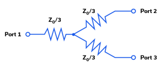
A resistive splitter uses a broadband resistor network.
Advantages can include:
Extremely wide bandwidth
Operation down to DC
Simple architecture
Excellent broadband behavior
Tradeoffs include:
Higher loss
Lower isolation than many Wilkinson-type designs
Lower RF power capability
Resistive splitters are useful where ultra-wide bandwidth is more important than minimum loss.
Many equal-amplitude power splitters use an architecture related to the Wilkinson power divider concept.
These designs provide:
Equal outputs
0° relative phase
Good output-port isolation
Good impedance matching
Low excess insertion loss
The internal isolation resistor absorbs power associated with imbalance or reflected energy between branches.
This provides excellent isolation but also affects combiner power handling.
LTCC – Low Temperature Co-Fired Ceramic splitters provide:
Compact size
Repeatable manufacturing
Rugged construction
Good RF performance
They are useful for high-volume surface-mount applications.
Mini-Circuits LTCC splitter families include models with RF power handling into the tens of watts.
MMIC power splitters provide highly repeatable semiconductor-based RF performance in very compact packages.
Benefits can include:
Ultra-wide bandwidth
Small size
Excellent amplitude balance
Excellent phase balance
High repeatability
Mini-Circuits MMIC splitters include packaged and bare-die solutions extending into microwave and mmWave frequencies.
Number of Ways
Determine the number of outputs or inputs required.
Common configurations include:
2-way
3-way
4-way
6-way
8-way
12-way
16-way
24-way
Avoid cascading unnecessary stages if a suitable higher-port-count device is available, but also evaluate total bandwidth, loss and power requirements.
Frequency Range
The splitter must provide required:
Isolation
Insertion loss
Amplitude balance
Phase balance
VSWR
over the entire operating band.
Mini-Circuits standard catalog products extend from DC to 67 GHz.
Insertion Loss
Consider both:
Theoretical splitting loss
Additional insertion loss above theoretical
when calculating total signal loss.
Isolation
Specify the minimum isolation required between output branches.
High isolation is especially important if the devices connected to the outputs can influence one another.
Amplitude Balance
Choose a product with sufficiently low amplitude unbalance for your system.
This is especially important for coherent and phase-sensitive applications.
Phase Balance
For phased arrays, LO networks and coherent processing, phase unbalance may be one of the most important selection criteria.
RF Power
Determine whether the product will be used primarily:
As a splitter
As a combiner
In both directions
If combining, also determine whether the signals are:
Coherent
Non-coherent
Same frequency
Different frequency
Phase controlled
before applying power ratings.
DC Pass
If DC power must share the RF path, choose a model specifically rated for DC pass-through.
Impedance
Choose 50 Ω or 75 Ω according to the complete RF system.
Mechanical Interface
Choose among:
Surface mount
Connectorized
Plug-in
MMIC die
according to system architecture.
RF Signal Distribution
Splitters distribute one RF signal to multiple receivers, instruments or system channels.
Local Oscillator Distribution
A stable LO source can be distributed to multiple mixers or receiver channels.
Low phase and amplitude unbalance are especially important in coherent systems.
RF Test & Measurement
Splitters and combiners are widely used in:
Automated test
Laboratory systems
Production test
Multi-channel measurements
Receiver testing
Calibration
Amplifier Power Combining
A combiner can combine the outputs of multiple RF amplifiers.
For efficient power combining, the amplifier outputs normally need carefully controlled:
Frequency
Amplitude
Phase
High-power systems may use dedicated non-isolating combiners.
Phased Arrays
Splitters distribute coherent RF signals among multiple array channels.
Important parameters include:
Phase balance
Amplitude balance
Isolation
Insertion loss
Radar
RF splitters and combiners are used in:
Signal distribution
LO networks
Receiver systems
Test systems
High-power amplifier networks
Wireless Communications
Applications include:
Base stations
Distributed RF networks
Multi-channel radios
Signal monitoring
Test systems
CATV & Broadband
75 Ω splitter / combiners support:
CATV
Broadband distribution
Video
Cable networks
mmWave Test & Measurement
1.85 mm splitter / combiners through 67 GHz support:
Semiconductor testing
5G / 6G research
Radar
mmWave instrumentation
Device characterization
A power splitter intentionally divides a significant portion of the input signal among multiple outputs.
A directional coupler normally samples only a defined fraction of the mainline signal.
For example:
Use a splitter when:
One signal must feed two equal channels.
Use a 20 dB directional coupler when:
Approximately 1% of the main signal needs to be sampled for monitoring.
An RF power splitter is a passive device that divides one RF input among multiple output ports.
Is a power divider the same as a power splitter?
In this context, yes.
The terms power splitter and power divider are generally used interchangeably.
Can a power splitter also be used as a combiner?
Many passive splitter / combiners are reciprocal and can be used in either direction.
However, combiner power handling depends on the signals being combined and must be checked separately.
What is the theoretical loss of a 2-way splitter?
An ideal 2-way equal splitter has approximately 3.01 dB theoretical power division loss per output.
Additional practical insertion loss is added to this value.
What is the theoretical loss of a 4-way splitter?
An ideal 4-way equal splitter has approximately 6.02 dB theoretical splitting loss per output.
What does insertion loss above theoretical mean?
It is the additional practical RF loss beyond the unavoidable theoretical splitting loss.
For example, a 2-way splitter with 0.5 dB excess insertion loss has approximately:
3.0 dB theoretical loss + 0.5 dB excess loss = 3.5 dB total path loss.
What is isolation in a power splitter?
Isolation describes how strongly one output port is isolated from another.
Higher isolation reduces interaction between connected devices.
What is amplitude unbalance?
Amplitude unbalance is the difference in output power between nominally equal output ports.
Lower values indicate more equal output levels.
What is phase unbalance?
Phase unbalance is the phase difference between outputs relative to the ideal phase relationship.
For a 0° splitter, outputs should ideally have the same phase.
Why is phase balance important?
Phase balance is especially important in:
Phased arrays
LO distribution
Coherent systems
Power combining
Multi-channel measurements
What is a DC-pass splitter?
A DC-pass splitter allows DC current to pass through one or more RF paths while also dividing the RF signal.
This can be useful for powering remote active equipment over RF coax.
What is the difference between a resistive and isolated splitter?
A resistive splitter can provide extremely wide bandwidth, including DC operation, but generally has greater loss and lower isolation.
An isolated splitter such as a Wilkinson-type architecture provides much higher output isolation and lower excess loss over its designed frequency range.
Can two amplifiers be combined with a splitter / combiner?
Yes, but their output signals generally need to be closely controlled in frequency, phase and amplitude.
Combining mismatched or out-of-phase signals can result in internal power dissipation and reduced output.
What happens if two equal signals are 180° out of phase?
In an ideal 0° combiner they can cancel at the output.
The associated power may then be dissipated inside the combiner, potentially exceeding internal component ratings.
What is the difference between coherent and non-coherent combining?
Coherent signals maintain a controlled phase and frequency relationship.
Non-coherent signals do not.
Combiner loss and internal dissipation can differ significantly between these conditions.
Is splitter maximum input power the same as combiner power rating?
No.
Never assume that the splitter rating applies when the product is used as a combiner.
Check the datasheet’s specific combiner rating and operating conditions.
What frequency range do Mini-Circuits power splitters cover?
The current standard Mini-Circuits power splitter / combiner catalog includes products from DC to 67 GHz.
Does Mini-Circuits offer 67 GHz power splitters?
Yes.
Mini-Circuits offers current 1.85 mm connectorized 2-way, 3-way, 4-way and 8-way splitter / combiner solutions covering 18 to 67 GHz.
How many outputs are available?
The standard catalog includes products up to 24 ways.
Selected special or non-catalog designs are available with higher port counts, including 48-way configurations.
Are 75 Ω power splitters available?
Yes.
Mini-Circuits offers selected 75 Ω splitter / combiner products for CATV and broadband applications.
Does Mini-Circuits offer high-power combiners?
Yes.
Mini-Circuits offers high-power isolated and non-isolating splitter / combiner solutions, including special products operating at power levels into the kilowatt range.
What is the difference between a power splitter and directional coupler?
A splitter divides a substantial fraction of the RF signal among multiple outputs.
A directional coupler normally samples only a controlled fraction of the mainline signal.
What is the difference between a 0° splitter and hybrid coupler?
A conventional splitter provides nominally equal-phase outputs.
A 90° or 180° hybrid intentionally provides a defined phase difference between outputs.
Can MCDI help select a splitter or combiner?
Yes.
MCDI’s Application Engineering team in Israel can help identify suitable Mini-Circuits splitter / combiners according to frequency, number of ways, isolation, loss, balance, power, impedance, DC pass and interface requirements.
Why Source Mini-Circuits RF Power Splitters Through MCDI?
MCDI is Mini-Circuits’ exclusive representative and distributor in Israel, providing Israeli engineers and purchasing teams with access to Mini-Circuits RF, microwave and millimeter-wave products together with local technical, commercial and logistical support.
Local Application Engineering
Splitter / combiner selection requires balancing:
Frequency
Number of ways
Isolation
Insertion loss
Amplitude unbalance
Phase unbalance
RF power
Combiner signal coherence
DC pass
Mechanical interface
MCDI’s Application Engineers can help identify suitable Mini-Circuits models.
Technical Support in Hebrew and English
Discuss your RF distribution or combining requirements directly with an Israel-based engineering team familiar with Mini-Circuits components and systems.
High-Power Combining Support
For amplifier combining and high-power systems, MCDI can help evaluate:
Coherent signal requirements
Non-isolating combiner architectures
Combiner dissipation
Amplifier phase matching
Thermal requirements
Complete RF Distribution Solutions
MCDI can also assist with:
Amplifiers
Attenuators
RF switches
Couplers
Filters
Phase shifters
RF cables
Custom signal-distribution systems
Support from Selection Through Delivery
MCDI supports customers in Israel from product selection and quotation through ordering, logistics and post-sales technical assistance.
Before you leave, you should know that MCDI’s professional team of Application Engineers will be delighted to assist you in sourcing the right component. Just fill the form and we will be back to you shortly.