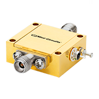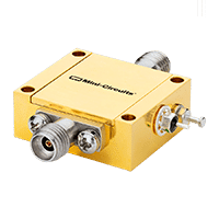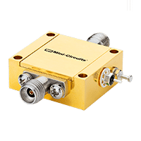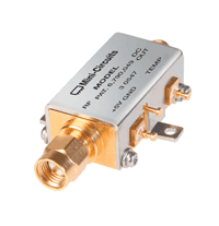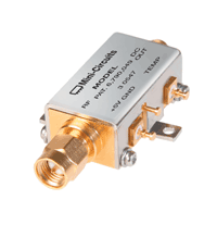

MCDI offers a selection of Mini-Circuits RF, microwave and millimeter-wave power detectors for RF power monitoring, signal-level measurement, automatic gain control, transmit-power control, RF leakage monitoring and fast feedback systems.
The portfolio includes fast envelope detectors and RMS power detectors, with coaxial solutions covering selected applications from 10 MHz to 67 GHz.
Available input-power ranges extend from approximately −60 dBm at the low end to +20 dBm at the high end, depending on the individual detector model.
Mini-Circuits power detectors convert an RF input signal into a corresponding analog output voltage, allowing the RF signal level to be monitored by control circuitry, an ADC, a data-acquisition system or test equipment.
Important selection parameters include:
MCDI’s Application Engineering team in Israel can assist you in selecting the appropriate Mini-Circuits power detector according to your RF waveform, frequency range, signal level, accuracy, response-time and control-system requirements.
Hebrew & English Professional Support
Get a quote within hours or less
DDP & Ex-Works - your choice
Custom Adapters & Catalog modifications
Access to Mini-Circuits full portfolio
Mini-Circuits Quality & Reliability
Use the RF Power Detector Catalog below to search and compare Mini-Circuits detectors according to your application requirements.
For complete detector transfer functions, frequency response, accuracy, response time, supply requirements and absolute maximum ratings, always review the individual Mini-Circuits product datasheet.
Search and compare according to:
An RF power detector converts the level of an RF or microwave signal into a lower-frequency or DC output voltage.
Conceptually:
RF Input Power → Detector → Analog Output Voltage
The output voltage can then be used by:
Unlike a complete digital power meter or USB power sensor, the detector is generally an RF component that becomes part of the customer’s analog or mixed-signal system.
The type of RF waveform being measured is one of the most important factors in selecting a detector.
Mini-Circuits offers both envelope / peak-type detectors and RMS detectors.
An envelope detector produces an output related to the instantaneous amplitude or envelope of the RF input signal.
For a simple continuous-wave – CW – signal whose amplitude is constant, this provides a useful representation of signal level.
Envelope detectors are particularly useful where fast response is important.
Applications include:
Mini-Circuits’ ZV47-K44+ is an ultra-wideband envelope detector covering 500 MHz to 43.5 GHz with a typical rise time of approximately 4 ns.
The ZX47 detector families provide additional wide-dynamic-range envelope-detection options through 8 GHz.
An RMS detector is better suited to applications where the RF waveform contains complex amplitude variation.
Rather than responding only to peak envelope amplitude, an RMS detector provides an output representing the signal’s average power based on its RMS voltage.
RMS detection is especially useful for signals such as:
Mini-Circuits’ RMS detector family includes:
ZV47-K44RMS+
100 MHz to 40 GHz
and:
ZV47-E673RMS+
100 MHz to 67 GHz
The ZV47-E673RMS+ provides a linear-in-dB response with a typical logarithmic slope of approximately 29 mV/dB across its specified dynamic range.
Choose an envelope detector when:
Choose an RMS detector when:
Selecting the wrong detector architecture can produce an output that does not accurately represent the quantity you intend to measure.
The dynamic range of a power detector identifies the span of RF input levels over which it provides useful specified performance.
Mini-Circuits commonly specifies:
Dynamic Range at ±1 dB Error
This indicates the input-power range over which the detector’s response remains within the specified ±1 dB error criterion under the stated conditions.
For example, a detector may specify:
−40 to +20 dBm
at ±1 dB error.
This represents a 60 dB input-power span.
Another detector may extend much farther toward low power but have a different maximum input level.
The correct range should therefore be selected according to both:
Across the current Mini-Circuits detector family, available input ranges include examples such as:
−40 to +20 dBm
−45 to +15 dBm
−50 to +10 dBm
−60 to +5 dBm
−30 to +15 dBm
−35 to 0 dBm
This means the overall portfolio provides options for systems requiring either:
Do not interpret −60 to +20 dBm as the dynamic range of a single detector unless the individual product datasheet explicitly specifies that range.
The detector converts RF signal level into an analog output voltage.
Depending on model, output ranges include values such as:
The following control or measurement circuit must be compatible with this voltage range.
Possible interfaces include:
Selected Mini-Circuits detectors provide an approximately linear-in-dB output response.
In this type of detector, equal changes in RF input power expressed in dB produce approximately equal changes in detector output voltage.
For example, an RMS detector may specify a slope such as:
29 mV/dB
This makes it convenient to convert detector voltage into estimated RF power using an ADC and calibration relationship.
Always use the individual detector’s specified transfer function and frequency-dependent calibration data when measurement accuracy is important.
Power-detector response time determines how quickly the output reacts when RF input level changes.
Mini-Circuits specifies:
depending on model.
Fast response is particularly important in:
The ZV47-K44+ provides an extremely fast typical response, including approximately:
4 ns rise time
and:
50 ns fall time
making it suitable for applications where rapid envelope detection is required.
RMS processing requires averaging or signal processing over a longer period than a simple fast envelope detector.
RMS detector response times can therefore be significantly slower.
For example, selected RMS models specify response times in microseconds rather than nanoseconds.
This is not necessarily a disadvantage.
It reflects the fundamentally different task of producing an accurate average-power representation of a complex waveform.
Choose detector architecture according to what must be measured, not solely according to the fastest response time.
Mini-Circuits offers standard and LN – Low Noise versions of several ZX47 detector models.
The low-noise versions are optimized for reduced output noise or ripple, while the standard versions may provide faster response.
For example, products in the same input-power family may show different:
This creates an important design tradeoff.
Choose a fast-response detector when loop speed is the primary requirement.
Choose a low-noise detector when a cleaner or more stable output voltage is more important.
Always compare the individual datasheets for your specific application.
The detector RF input becomes part of the RF signal path or measurement network.
Good input matching helps reduce:
Mini-Circuits specifies detector input VSWR across the operating band.
At millimeter-wave frequencies, mismatch becomes particularly important and should be included in the measurement uncertainty budget.
The upper end of a detector’s specified measurement or ±1 dB dynamic range is not necessarily the same as its absolute maximum RF input rating.
For example, a detector may be characterized accurately only to:
0 dBm
while tolerating a somewhat higher RF level before damage occurs.
The absolute maximum rating is a damage limit, not an accuracy specification.
Always verify both:
in the individual datasheet.
Mini-Circuits active power detectors require DC power.
Depending on model, current detector families use supplies such as:
with current consumption ranging from only a few milliamps to approximately 100 mA.
When integrating the detector, provide:
Power-supply noise can affect sensitive analog measurements.
Mini-Circuits’ current ZV47-E673RMS+ extends RMS power detection to 67 GHz.
The detector uses a 1.85 mm RF input interface and provides a DC output proportional to average RF signal power.
Its operating range makes it suitable for applications including:
For frequencies approaching 67 GHz, connector care, torque, adapters and cable performance become critical parts of the complete measurement setup.
First determine whether the RF signal is:
This determines whether a fast envelope detector or RMS detector is more appropriate.
The detector must cover the complete RF frequency range of the signal.
Mini-Circuits currently offers selected coaxial detectors covering:
depending on model and detector architecture.
Determine:
Then select a detector whose specified dynamic range contains the complete normal operating range.
If measurement accuracy is important, pay particular attention to:
Fast feedback and pulse applications may require nanosecond-scale response.
Average-power monitoring of modulated signals may prioritize RMS accuracy over response speed.
Make sure the detector’s output range is compatible with the receiving electronics.
For ADC-based monitoring, consider:
Current Mini-Circuits detector families use precision coaxial interfaces including:
depending on frequency range.
Use high-quality cables and adapters appropriate to the operating frequency.
A common RF power-monitoring architecture combines a directional coupler with a power detector.
For example:
Transmitter → Directional Coupler → Antenna
with:
Coupled Port → RF Power Detector → ADC / Control Circuit
The directional coupler samples only a fraction of the high-power RF signal.
The detector then converts this lower-power sample into an analog voltage.
This architecture can be used for:
A bi-directional or dual-directional coupler can provide separate samples of:
Separate power detectors can convert these two sampled signals into control voltages.
A processor or analog circuit can then evaluate:
This architecture is frequently used in transmitter-monitoring and protection systems.
RF power detectors can form part of an automatic gain control loop.
A typical architecture may be:
RF Signal → Amplifier / Mixer → Detector
with the detector output feeding:
Integrator / Controller → Variable Attenuator or Variable-Gain Amplifier
If detected RF level rises above the desired value, the controller reduces gain or increases attenuation.
If RF level falls, the controller adjusts in the opposite direction.
This enables the system to maintain a relatively constant signal level.
A detector can monitor transmitter output and provide a feedback voltage to regulate RF power.
Applications include:
The detector architecture should match the transmitted waveform.
For complex modulated signals, an RMS detector may be more appropriate than a simple peak/envelope detector.
A power detector can also determine whether RF energy is present at a monitoring point.
Applications include:
The required detector sensitivity should be selected according to the lowest RF level that must reliably be detected.
An RF power detector and an RF power sensor serve related but different purposes.
A detector is generally an analog RF component.
It provides:
RF Input → Analog Output Voltage
The user integrates this voltage into their own:
A power sensor is a more complete measurement instrument.
Mini-Circuits USB / Ethernet smart power sensors can include:
Available power sensors support CW, RMS, peak and average measurement depending on model.
Which Should I Use?
Choose a power detector when:
Choose a power sensor when:
Power detectors provide an analog representation of RF signal level for embedded measurement applications.
A detector combined with a directional coupler can continuously monitor transmitter output.
Detector feedback can be used to control receiver gain or attenuation and maintain desired signal level.
Fast envelope detectors can be useful for:
while RMS detectors can support suitable average-power measurement applications.
Wideband RMS detectors can monitor the average power of complex communication waveforms used in modern wireless systems.
Ultra-wideband detectors can provide power monitoring and gain-control feedback throughout microwave transmitter and receiver systems.
Power detectors can be integrated into:
A detector output can be compared with a reference voltage in a feedback loop to maintain a controlled RF signal level.
An RF power detector converts RF signal level into an analog DC or baseband voltage that can be measured or used by a control circuit.
Mini-Circuits’ current coaxial detector portfolio includes selected models covering frequencies from 10 MHz to 67 GHz.
Yes.
The ZV47-E673RMS+ is an RMS power detector covering 0.1 to 67 GHz with a 1.85 mm RF input interface.
An envelope detector provides an output related to the instantaneous amplitude or envelope of an RF signal.
It is useful for CW measurement, pulse detection and fast monitoring or feedback applications.
An RMS detector provides an output corresponding to the signal’s average power based on its RMS voltage.
It is especially useful for complex modulated waveforms.
An RMS detector is generally more appropriate when accurate average-power measurement of complex modulated signals such as OFDM or QAM is required.
Fast envelope detectors can respond much faster than RMS detectors.
For example, selected envelope detectors provide nanosecond-scale response, while RMS detectors may respond on a microsecond time scale.
The correct choice depends on the measurement requirement.
It is the RF input-power range over which the detector response meets the specified ±1 dB error criterion under the defined measurement conditions.
Not necessarily.
Across the portfolio, different models cover different ranges.
Some extend down to approximately −60 dBm, while others accept levels as high as approximately +20 dBm.
Always check the range of the specific model.
A linear-in-dB detector produces an output voltage that changes approximately linearly with input power expressed in dB.
This simplifies conversion between measured detector voltage and RF input power.
It describes detector output slope.
For example, 29 mV/dB means that a 1 dB change in RF input power produces approximately a 29 mV change in detector output voltage within the specified range.
Response time determines how quickly the detector output reacts to changes in RF signal level.
Fast response is important in pulse monitoring, fast AGC and high-speed feedback systems.
Rise time describes the output response when RF level increases.
Fall time describes the response when RF level decreases.
They may be significantly different.
LN models are optimized for lower output noise or ripple, while standard models may provide faster response.
The tradeoff should be evaluated using the individual datasheets.
Yes.
This is one of the most common RF power-monitoring architectures.
The coupler samples part of the main RF signal, and the detector converts the sampled signal into a voltage for measurement or control.
Yes.
A detector can measure RF level and provide feedback to a variable attenuator or variable-gain amplifier in an automatic gain-control loop.
A power detector is usually an analog component that provides an output voltage proportional to RF level.
A smart power sensor is a calibrated measurement instrument with digital control, software and direct power readout.
Yes.
MCDI also offers Mini-Circuits USB and Ethernet smart power sensors for CW, RMS, peak and average measurements, depending on model.
Yes.
MCDI’s Application Engineering team in Israel can help identify suitable Mini-Circuits detectors according to waveform, frequency, RF power range, accuracy, response time and interface requirements.
MCDI is Mini-Circuits’ exclusive representative and distributor in Israel, providing Israeli engineers and purchasing teams with access to Mini-Circuits RF, microwave and millimeter-wave products together with local technical, commercial and logistical support.
Local Application Engineering
Power-detector selection depends strongly on the RF waveform and intended use.
MCDI’s Application Engineers can help evaluate:
and identify suitable Mini-Circuits products.
Technical Support in Hebrew and English
Discuss your RF monitoring or measurement application directly with an Israel-based engineering team familiar with Mini-Circuits detectors and complete RF signal chains.
Complete Power-Monitoring Solutions
MCDI can also assist with related Mini-Circuits products including:
allowing the detector to be evaluated as part of the complete monitoring or feedback architecture.
Millimeter-Wave Support
For applications extending into mmWave frequencies, MCDI can assist with the detector together with the appropriate precision cables, adapters, couplers and other RF interconnect products.
Support from Selection Through Delivery
MCDI supports customers in Israel from product selection and quotation through ordering, logistics and post-sales technical assistance.




Before you leave, you should know that MCDI’s professional team of Application Engineers will be delighted to assist you in sourcing the right component. Just fill the form and we will be back to you shortly.