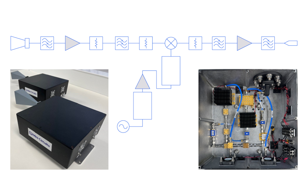

MCDI offers a broad selection of Mini-Circuits RF, microwave and millimeter-wave frequency multipliers for generating higher-frequency signals from lower-frequency RF sources.
The portfolio includes frequency doublers (X2), triplers (X3), quadruplers (X4), X5, X7 and X12 multipliers, with connectorized, surface-mount, plug-in and MMIC bare-die configurations.
Selected Mini-Circuits frequency multiplier solutions provide output frequencies from 100 kHz to 72 GHz, with products optimized for low conversion loss, strong fundamental rejection and suppression of unwanted harmonics.
Frequency multipliers are widely used in local oscillator generation, frequency synthesizers, radar, satellite communications, test equipment, microwave signal sources and millimeter-wave systems.
MCDI’s Application Engineering team in Israel can assist you in selecting the appropriate frequency multiplier according to input frequency, required output frequency, multiplication factor, available input power, conversion loss, harmonic suppression, package and application.
Hebrew & English Professional Support
Get a quote within hours or less
DDP & Ex-Works - your choice
Custom Adapters & Catalog modifications
Access to Mini-Circuits full portfolio
Mini-Circuits Quality & Reliability
Use the Frequency Multiplier Catalog below to search and compare Mini-Circuits products according to your application requirements.
Search and filter according to:
For complete frequency, input-power, conversion-loss, output-power, harmonic-suppression, VSWR, environmental and absolute maximum specifications, always review the individual Mini-Circuits product datasheet.
An RF frequency multiplier is a nonlinear device that generates an output signal whose frequency is an integer multiple of its input frequency.
The basic relationship is:
FOUT = N × FIN
where:
For example:
A 2 GHz signal applied to an X3 frequency tripler produces a desired output at:
2 GHz × 3 = 6 GHz
The nonlinear multiplier also generates other harmonics of the input signal. A well-designed frequency multiplier is therefore optimized to provide the desired harmonic while suppressing the fundamental and unwanted neighboring harmonics.
Generating a lower-frequency signal can sometimes be easier than generating the final required microwave or millimeter-wave frequency directly.
A multiplier allows a stable lower-frequency source to be translated to a higher frequency.
Potential advantages include:
Frequency multipliers are therefore commonly used together with:
A frequency doubler produces a desired output at twice the input frequency:
FOUT = 2 × FIN
Frequency doublers are among the most widely used multiplier types.
Applications include:
Mini-Circuits offers X2 multipliers over a broad range of input and output frequencies in surface-mount, connectorized and MMIC configurations.
When choosing a frequency doubler, review:
A frequency tripler generates the third harmonic of the input signal:
FOUT = 3 × FIN
Mini-Circuits offers both passive and active X3 multiplier solutions for RF, microwave and millimeter-wave applications.
Selected connectorized triplers provide outputs through 72 GHz.
Typical applications include:
At higher frequencies, pay particular attention to input-power range, conversion loss, fundamental suppression and suppression of the second and fourth harmonics.
An X4 multiplier, or quadrupler, produces:
FOUT = 4 × FIN
X4 multiplication can provide a convenient alternative to cascading two separate X2 multipliers.
Potential benefits include:
The appropriate solution depends on input frequency, required output frequency, available drive power and suppression requirements.
Higher multiplication factors allow a much lower-frequency source to generate a significantly higher-frequency output.
Mini-Circuits offers selected:
These products can simplify architectures in which a high multiplication ratio is required without cascading several discrete multiplier stages.
As multiplication factor increases, designers should carefully consider:
A lower multiplication factor combined with multiple stages may sometimes provide different system-level tradeoffs than a single higher-order multiplier.
MCDI’s Application Engineers can help evaluate the most suitable architecture.
Most traditional RF multipliers are passive nonlinear components.
They do not require a DC supply and typically convert some of the input RF power into the desired harmonic.
Because the desired output is lower in power than the applied input signal, passive multipliers are normally characterized by conversion loss.
Benefits of passive multiplier architectures can include:
A sufficient RF input level must be available to drive the multiplier within its specified operating range.
An active frequency multiplier incorporates powered circuitry in addition to the nonlinear multiplier function.
This may include amplification before or after the multiplication stage.
Potential benefits include:
Active multipliers require a DC supply and should therefore also be evaluated according to:
Mini-Circuits offers selected active multiplier solutions for wideband microwave and millimeter-wave applications.
Connectorized multipliers are convenient for:
They allow frequency multiplication to be added directly into a coaxial signal chain without PCB-level integration.
Mini-Circuits offers connectorized multipliers with output frequencies extending through 72 GHz.
Surface-mount multipliers are suitable for PCB-level integration in production equipment.
Benefits include:
Mini-Circuits surface-mount families include multiplier solutions for both lower-frequency RF and microwave applications.
Mini-Circuits also offers selected MMIC bare-die multipliers for hybrid microwave, chip-and-wire and highly integrated high-frequency designs.
Bare die can be useful where:
Custom modules are being designed
What Is Conversion Loss?
For a passive multiplier, conversion loss describes the difference between the applied input power and the power available at the desired multiplied output frequency.
For example:
If:
then the approximate desired output level would be:
+15 dBm − 12 dB = +3 dBm
under the specified operating conditions.
Lower conversion loss generally provides more available output power.
Conversion Loss Varies with Frequency and Input Power
Conversion loss is not necessarily constant across the multiplier’s complete operating range.
It may vary according to:
Always review the performance curves in the individual datasheet when system output-power margin is important.
A frequency multiplier generates more than only the desired harmonic.
For an X3 multiplier, for example, the desired output is the third harmonic:
F3 = 3 × FIN
But the output may also contain:
The multiplier is designed to maximize the desired F3 component while suppressing these unwanted signals.
Fundamental suppression indicates how far below the desired multiplied output the original input-frequency component appears.
For example:
F1 suppression = 40 dBc
means the residual fundamental component is approximately 40 dB below the desired output harmonic.
Higher suppression is generally better.
For an XN multiplier, the most relevant neighboring harmonics may be described as:
F[N−1] and F[N+1]
For example, for an X3 multiplier:
Strong suppression of these neighboring harmonics helps reduce the filtering required after the multiplier.
Frequency multiplication also affects phase noise.
For an ideal multiplier with multiplication factor N, phase noise referred to the multiplied carrier increases theoretically by approximately:
20 × log10(N) dB
For example:
relative to the input source, before considering any additional noise contributed by the actual multiplier circuitry.
This means the phase-noise performance of the original oscillator or synthesizer becomes especially important when generating high-frequency signals through multiplication.
For phase-noise-sensitive applications such as:
the complete source-plus-multiplier chain should be evaluated.
Start with the frequency you need to generate.
For example, if you require:
36 GHz output
possible architectures could include:
The best architecture depends on available source frequency, power, phase noise, filtering and system complexity.
Choose the multiplication factor according to the available input frequency and required output.
Higher multiplication factors can reduce the frequency required from the source but may involve different:
The source frequency must remain within the multiplier’s specified input range.
For tunable applications, confirm that the multiplier supports the entire required input-frequency sweep.
Verify that the desired multiplied output remains within the specified output-frequency range.
Do not assume that a multiplier works correctly at every harmonic over unlimited bandwidth.
Frequency multipliers require the input signal to fall within a specified power range.
Too little input power may result in:
Too much input power may degrade performance or exceed the device’s maximum rating.
Check both:
throughout the operating band.
Conversion loss directly affects the output power available at the desired harmonic.
Include conversion loss in the complete system power budget.
If additional output level is required, amplification may be placed before or after the multiplier depending on the architecture.
Strong fundamental suppression reduces the amount of residual input-frequency energy appearing at the multiplier output.
This can simplify output filtering and improve spectral purity.
Review the suppression of relevant unwanted harmonic products, especially those immediately adjacent to the desired harmonic.
For an X3 multiplier, for example, examine:
suppression.
Even a multiplier with strong internal harmonic suppression may require an external filter when very high spectral purity is required.
A suitable:
can help isolate the desired harmonic.
[BUTTON: EXPLORE RF FILTERS]
Because phase noise increases with multiplication factor, consider the phase-noise performance of the source.
If the final high-frequency output must have very low phase noise, begin with a source having sufficient phase-noise margin.
Spurious signals already present at the multiplier input may also produce unwanted products at the output.
A clean input source and appropriate pre-filtering may therefore improve final spectral purity.
Choose the mechanical interface appropriate for the application:
Connectorized products are particularly useful for laboratory and system-level integration, while surface-mount and die products are more appropriate for compact production designs.
Frequency multipliers are widely used to generate higher-frequency LO signals for:
A lower-frequency synthesizer or oscillator can be multiplied to generate the required microwave or mmWave LO.
A multiplier can extend the output range of a frequency synthesizer.
For example, a synthesizer covering a lower microwave band can be followed by an X2 or X3 multiplier to reach significantly higher frequencies.
Radar systems often require stable microwave or millimeter-wave sources.
Multipliers can generate higher-frequency LO or transmit-reference signals from lower-frequency sources.
Important radar considerations include:
Frequency multipliers can be used in SATCOM frequency-generation chains, including local oscillator systems and up/down-converter architectures.
Wideband microwave and millimeter-wave multipliers can extend available test sources into higher-frequency bands for:
Connectorized frequency multipliers allow engineers to extend available signal generators and synthesizers into higher-frequency bands.
This can be useful in:
Multipliers can form part of a signal-generator architecture where a lower-frequency synthesized source is amplified, multiplied and filtered to obtain the required output band.
Frequency multipliers can support broadband and frequency-agile LO-generation chains where wide output coverage and strong harmonic suppression are important.
A frequency multiplier and a frequency mixer are both nonlinear RF components, but they perform different functions.
A multiplier uses harmonics of a single input signal to generate a desired output at:
N × FIN
For example:
10 GHz input → X3 multiplier → 30 GHz output
A mixer combines two separate input frequencies, typically RF and LO, and generates sum and difference products such as:
RF + LO
and:
|RF − LO|
Use a multiplier when the required output must be harmonically related to one source.
Use a mixer when frequency translation between independent signals is required.
A practical multiplier chain often contains more than the multiplier itself.
A typical architecture may include:
Oscillator / Synthesizer → Amplifier → Multiplier → Filter → Amplifier
An amplifier before the multiplier can provide the required drive level.
A filter after the multiplier can suppress:
An amplifier after filtering can increase the final signal level to the required output power.
MCDI can assist with all of these Mini-Circuits signal-chain components.
An RF frequency multiplier is a nonlinear component that produces a desired output signal at an integer multiple of the applied input frequency.
A frequency doubler is an X2 multiplier.
For example:
5 GHz input → 10 GHz output.
A frequency tripler is an X3 multiplier.
For example:
10 GHz input → 30 GHz output.
An X4 multiplier generates an output at four times the input frequency.
It may also be called a frequency quadrupler.
Mini-Circuits currently offers frequency multiplier solutions including X2, X3, X4, X5, X7 and X12 multiplication factors.
Availability and frequency range depend on the individual model.
Mini-Circuits currently offers frequency multiplier products with output frequencies from approximately 100 kHz to 72 GHz, depending on multiplication factor and model.
Yes.
Selected Mini-Circuits connectorized X3 multiplier models provide output frequencies through 72 GHz.
Conversion loss is the difference between RF input power and the power available at the desired multiplied output frequency.
Lower conversion loss generally provides greater available output power.
The nonlinear elements inside the multiplier need an appropriate drive level to efficiently generate the desired harmonic.
Insufficient or excessive drive can degrade conversion loss and harmonic suppression.
Fundamental suppression indicates how far below the desired multiplied output the original input-frequency signal appears at the output.
Higher fundamental suppression generally means better spectral purity.
Harmonic suppression indicates how effectively undesired harmonic products are reduced relative to the desired multiplied output.
No.
A nonlinear multiplier naturally generates multiple harmonics.
The device is designed to emphasize one desired harmonic and suppress others, but external filtering may still be required in demanding applications.
Yes.
For ideal frequency multiplication by a factor N, phase noise relative to the carrier increases theoretically by approximately 20 log10(N).
The actual system may also include additional noise contributed by the multiplier and surrounding circuitry.
Passive frequency multipliers normally do not require a DC supply.
They require sufficient RF input power to drive the nonlinear multiplication process.
An active multiplier includes powered circuitry such as amplification in addition to the frequency-multiplication function.
This can reduce the RF input-power requirement or provide other system-level benefits.
A multiplier generates a harmonically related output from one input signal.
A mixer combines two independent signals and generates sum and difference frequency products.
Yes.
Extending the frequency range of an oscillator or synthesizer is one of the common uses for an RF frequency multiplier.
It depends on the required spectral purity.
Even when the multiplier provides strong built-in harmonic suppression, a band-pass, low-pass or high-pass filter may be required when unwanted harmonics must be further reduced.
Yes.
MCDI’s Application Engineering team in Israel can help identify suitable Mini-Circuits multipliers according to input/output frequency, multiplication factor, input power, conversion loss, harmonic suppression, phase noise and mechanical interface requirements.
MCDI is Mini-Circuits’ exclusive representative and distributor in Israel, providing Israeli engineers and purchasing teams with access to Mini-Circuits RF, microwave and millimeter-wave products together with local technical, commercial and logistical support.
Local Application Engineering
Frequency-multiplier selection requires balancing:
MCDI’s Application Engineers can help evaluate these parameters and identify suitable Mini-Circuits products.
Technical Support in Hebrew and English
Discuss your frequency-generation requirements directly with an Israel-based engineering team familiar with Mini-Circuits components and complete RF signal chains.
Complete Frequency-Generation Support
MCDI can also assist with related Mini-Circuits products including:
allowing the multiplier to be evaluated as part of the complete frequency-generation architecture.
Special & Custom Solutions
If a catalog product does not meet your frequency, power, harmonic or mechanical requirements, MCDI can assist with evaluation of available special and custom Mini-Circuits solutions.
Support from Selection Through Delivery
MCDI supports customers in Israel from product selection and quotation through ordering, logistics and post-sales technical assistance.




Before you leave, you should know that MCDI’s professional team of Application Engineers will be delighted to assist you in sourcing the right component. Just fill the form and we will be back to you shortly.