A Quick Guide to RF & Microwave Filter Topologies
RF / microwave filters are essential building blocks of practically every wireless transceiver design. Filters block undesired signals outside the application operating bandwidth while passing in-band signals through to the rest of the signal chain. At a high level, filters can be described by their response, that is, the general shape of the S21 curve in the passband, transition, and stopband. A theoretically ideal filter would have a “brick wall” response, exhibiting 0 dB insertion loss in the passband, infinite rejection beyond the frequency cut-off fc and a transition from the passband to the stopband in 0 Hz, as depicted in Figure 1.
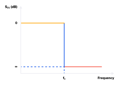
In reality, RF filters are subject to the constraints of the circuit topology used to realize the physical device, as well as other factors including the finite self-resonant frequency (SRF) of surface mount (SMT) capacitors, the finite quality factor (Q) of SMT inductors, and the parasitics associated with the printed circuit board (PCB), substrate materials, and packaging used to house the filter. This brief guide will focus on the basic performance characteristics of the common topologies used to design RF filters, as well as the general application requirements each topology can (and can’t) support.
Butterworth Filters (Maximally Flat or Monotonic)
Based on the Butterworth polynomial, this response has the flattest possible passband response for a given filter complexity. The Butterworth filter has a “maximally flat” passband response, which means that it has no ripple in the passband.
As the order of a Butterworth filter is increased, the sharpness of the transition increases in kind as shown in Figure 2. Curve A is a first-order filter with a roll-off of 6 dB per octave, while curve B is a second-order filter with a roll-off of 12 dB per octave, and so on. For higher order filters, the roll-off is (6*N) dB per octave, where N is the order of the filter. The Butterworth filter structure can be used to create low pass, high pass, bandpass, and band-stop filters.
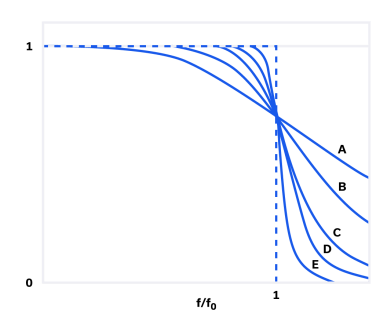
Although the Butterworth’s passband is very flat, it is not capable of achieving rejection curves as steep as some of the other filter topologies discussed below. In order to achieve “steep skirts”, a Butterworth filter must be high-order, which often means sacrificing insertion loss in the passband.
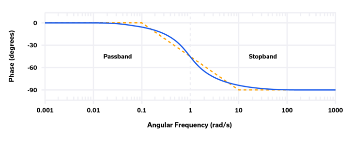
Like most of the other filter types, Butterworth filters do not have a linear phase response in the passband, though their phase response is more linear than for some other filter types. The phase response of a first-order Butterworth filter, centered at 1 radian per second (~0.16 Hz), is shown below in Figure 3:
Any RF transceiver where in-band gain flatness is critical, transition roll-off and stopband rejection are desirable, and in-band phase response is of secondary concern can take advantage of the characteristics of Butterworth filters. Butterworth filters are also suitable for use as anti-alias filters in an ADC where gain flatness is required and filtering of signals outside of the Nyquist region prevents problems due to aliasing.
Chebyshev Filters Type 1 (Equal Ripple)
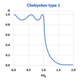
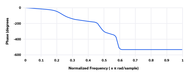
The Type 1 Chebyshev filter is typically referred to simply as “Chebyshev,” and is based on the Chebyshev polynomials. It has some ripple in the passband, but exhibits steeper roll-off and higher attenuation in the stopband than does the Butterworth filter. It also has higher insertion loss in the passband than an equivalent Butterworth filter. This can be seen in the Chebyshev filter frequency response shown in Figure 4. The phase response for the Chebyshev filter is far from linear as shown in Figure 5.
The typical application for a filter with Chebyshev Type 1 characteristics is one where in-band gain ripple is acceptable, but the stopband roll-off is critical in order to filter out-of-band spurious emissions and other types of interference. A receiver front end before the LNA input at the antenna is one such example.
Chebyshev Filters Type 2 (Inverse Chebyshev)
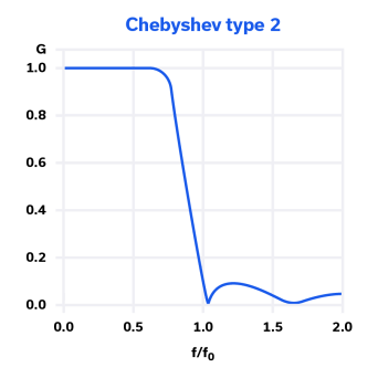
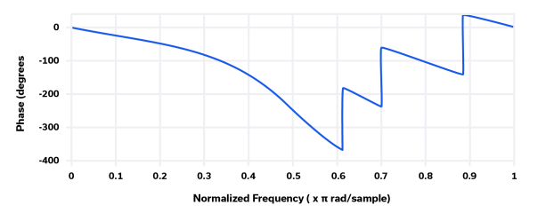
The Chebyshev Type 2 filter is less common than the Chebyshev Type 1 filter because it does not have as steep a roll-off as Type 1. It also requires more elements to construct than a Chebyshev Type 1 filter. The benefit of this topology, however, is that by inverting the classic Chebyshev response, it eliminates ripple in the passband. The transfer function for the Chebyshev Type 2 filter is shown in Figure 6. The phase response, shown in Figure 7 is also poor.
The Chebyshev Type 2 filter has many low frequency applications such as bridge sensors and filtering of electrocardiogram (EKG) signals.
Elliptic Filters
The elliptic filter response (Figure 8) is characterized by equal ripple in both the passband and stopband, but the amount of ripple in the passband and stopband is independently adjustable. For the same order filter, the elliptic filter has the steepest slope of all the topologies discussed here, which makes it useful for many applications. Many more elements are required to implement this type of filter than a Chebyshev Type 1 filter, which makes it more complicated and expensive to design and manufacture, but this may be a desirable tradeoff where precise selectivity is needed.
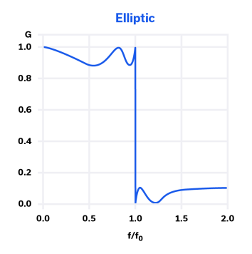
The phase response for the elliptic filter is similar to that of the Chebyshev Type 1, so it’s not ideal for applications where constant group delay is needed. Elliptic filters are ideal for use with power amplifiers (PA) in wideband RF transmitters. The filter characteristic supports PA operation over a wide bandwidth while filtering out-of-band harmonics for the PA when operating at the minimum frequency.
Bessel Filters (Linear Phase)
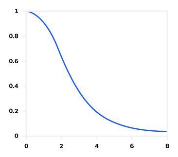
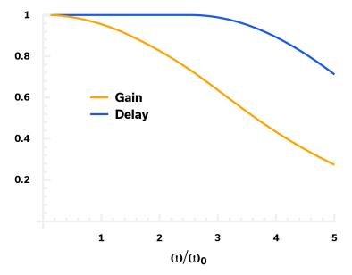
The Bessel filter response has the gentlest slope (lowest selectivity) of all the common topologies as shown in Figure 9. It’s advantage, however, is maximally flat group delay within the passband. The group delay for a typical Bessel filter is plotted versus frequency in Figure 10 and is defined as:
D = dΦ / dω
Where Φ is phase shift and ω is angular frequency. The group delay is constant, D = 1 in the passband for a Bessel filter, which best preserves the phase of the signal from input to output.
The Bessel filter is used in applications such as analog video signal processing and audio crossover filtering, which split signal into multiple bands that do not overlap. Constant group delay for each of these split bands is critical.
Mini-Circuits offers one of the industry’s widest selections of RF / microwave filters, including models exhibiting each of the topologies described here. S21 curves are provided for every model, and you should now be able to recognize the different response types for filters of interest for your application.


