Choosing an LNA for your Receiver Front End
Gary Cox, Field Applications Engineer, Mini-Circuits Japan
Background: Why the LNA Matters
A low-noise amplifier (LNA), which Mini-Circuits defines as any amplifier with a noise figure (NF) below 3 dB, should usually be used at the front end of an RF or microwave receiver chain for ideal performance. This single component has outsized effects on the rest of the signal chain, and that’s why choosing an LNA is such a critical decision. Mini-Circuits stands ready to help our customers through this process, so let’s take a look at what goes into it.
To understand the importance of the LNA, consider a series of cascaded amplifiers making up the front end of a receiver. To calculate the overall noise factor of the whole chain, we can take the gain (G) and noise factor (F) of each individual amplifier and apply Frii’s formula for noise as shown in Figure 1.
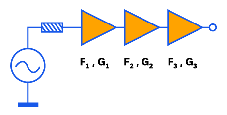

Figure 1: Frii’s formula for noise factor for a cascaded receiver signal chain.
Notice how the first summand (F1) – which is the only summand incorporating the first amplifier’s noise factor – is also the summand with the smallest denominator (that is, 1). Meanwhile, each subsequent summand – which incorporate the subsequent amplifiers’ noise factors –will always have a denominator greater than the one before it (assuming all amplifiers have positive gain). It’s therefore clear that, all other things being equal, each subsequent summand’s overall value is increasingly hampered by the denominator – ergo, the first amplifier has the greatest opportunity to increase your overall system’s noise factor.
Understood intuitively rather than mathematically, the noise introduced by the first amplifier is amplified by each of the subsequent amplifiers as well. At the same time, the greater the gain of the first amplifier, the greater the signal-to-noise ratio (SNR) of the first amplifier’s output can be (which gives more “room” for the noise contributions of subsequent amplifiers). In other words, the first amplifier’s output is the baseline or “starting off point” from which all subsequent amplifiers have to work from. Thus, it makes sense why the first receiver should be an LNA, and it’s why designers spend so much time finding the ideal combination of noise figure and gain performance choosing it. Additional requirements for other parameters like DC power consumption, output power at 1 dB compression, and output IP3 over operating bandwidth can further complicate the selection process.
How Signal and Noise Interact with the LNA
No matter how low its noise figure, an LNA cannot reduce the SNR of the signal coming into it (that is, it cannot perform miracles). The LNA – just like any other amplifier – will increase the power of the incoming signal and the incoming noise by the same amount (because an amplifier cannot “tell the difference” between the two). It will also add a small amount of noise itself, which we express as the LNA’s noise figure (with noise figure simply being the noise factor, expressed as F1 in Figure 1, in decibels).
Figure 2 illustrates this decrease in SNR due to the LNA. The left side of Figure 2 shows the LNA input’s signal and thermal noise. The LNA then increases the input signal power as well as the input’s thermal noise by the same amount – this is the gain. But, the LNA contributes some of its own thermal noise too – this is the noise figure. The right side of Figure 2 shows the resulting output.

Choosing the Right LNA Model for Your Requirements
The most critical LNA requirements we often see from our customers are for gain (G), noise figure (NF), size, and cost. Other common requirements we see are for third-order intercept point (IP3), DC power consumption, and output power at 1dB compression (P1dB). In an ideal world, an LNA would offer the perfect combination of all these parameters. The real world isn’t quite the same, though, and there will be necessary trade-offs between the parameters of LNAs. We can help guide receiver designers in weighing these tradeoffs to best meet their requirements.
Tradeoffs between parameters in amplifier performance are interlinked like a complex web. We’ve provided a very simplified look, with a tailored focus for LNAs, in Figure 3.
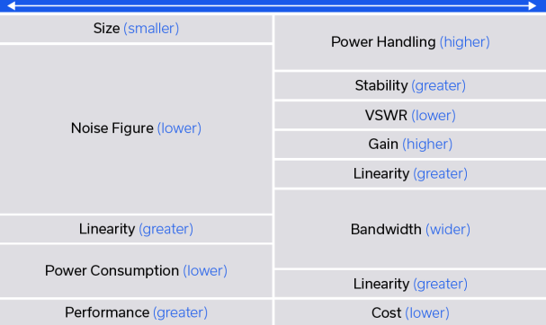
For example, if space is at a premium, the designer may find it best to choose the compact form factor of a MMIC LNA instead of a larger, connectorized LNA with higher power handling. Or, suppose they are designing a phased array radar receiver with 1,000 elements. In this case, 1,000 LNAs would be needed, and so the DC power consumption of the chosen model would be multiplied by 1,000x in the overall system power budget. This may drive the decision to select a model with lower power consumption at the expense of other parameters like linearity and P1dB.
Designers often face a tradeoff between bandwidth and performance, and LNAs are no exception. An LNA design can either be wideband or optimized to a specific band, and both approaches have benefits and drawbacks. Band optimized LNA designs can typically achieve lower noise figure and greater linearity than wideband designs. Power consumption is also typically lower in narrower band designs. Such narrow-band LNAs are thus a good fit when designing receivers for specific bands like L, C, Ku, or Ka band – but might not work for, say, software defined radio (SDR) applications where a single wideband LNA is required to cover a much wider bandwidth.
Mini-Circuits LNAs
Mini-Circuits offers one of the industry’s broadest selections of LNAs, including designs for specific application bands as well as wideband models with outstanding all-around performance.
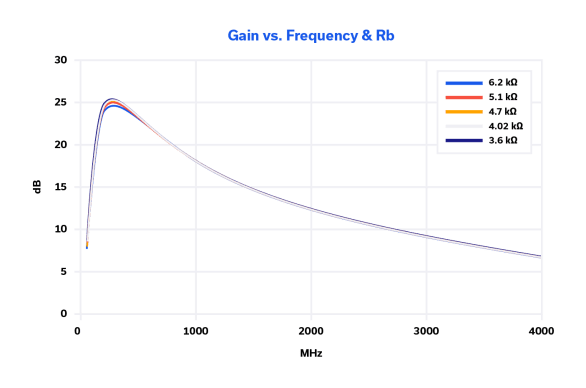
The PMA2-33LN+ LNA is a good example of an LNA that can be used in narrow bandwidth applications. The NF is less than 1 dB in the 0.9 – 3 GHz frequency range, achieving a minimum noise figure of 0.36 dB at 1.5 GHz. The typical P1dB across this bandwidth is 17 dBm and the OIP3 varies between 30 and 39 dBm, with DC power consumption around 170 mW. The gain response in Figure 4 illustrates this product’s tuned design.
The PMA3-83LN+ is a good example of a wideband LNA. The noise figure is typically 1.5 dB in the 0.5 – 8 GHz frequency range and achieves a minimum noise figure of 1.3 dB at 2 GHz – an exceptional figure in this frequency range. The typical P1dB across this bandwidth is 18-20 dBm and the OIP3 varies between from 28 to 34 dBm, with DC power consumption of 300 mW.
Finally, a recent example of a wideband LNA design is our PMA3-453+, which we designed to cover an extremely wide frequency range while still achieving excellent RF performance. The noise figure for this model ranges from 1.6 to 5.2 dB in the 10 – 45 GHz frequency range, achieving a minimum noise figure of 1.6 dB at 20 GHz. The typical P1dB across this bandwidth is 8.5 to 12.7 dBm and the OIP3 varies between 18.6 and 23.4 dBm. DC power consumption is 475 mW, a higher power dissipation that’s attributed to this product’s wider bandwidth.
When selecting the best LNA for their receiver, it will help the designer to keep these parameters’ correlation patterns in mind.
Conclusion
The right choice for an LNA is not always obvious. The system designer must take into account many considerations including the system application, electrical requirements, mechanical requirements, and cost. Mini-Circuits’ vast LNA product portfolio provides the designer with the widest spectrum of options on the market today, and we’re always ready to lend our experience in this process.


