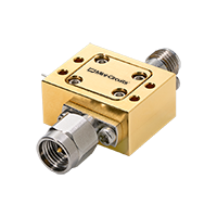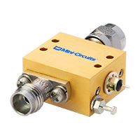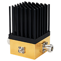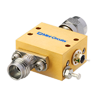

MCDI offers a broad selection of Mini-Circuits RF, microwave and millimeter-wave bias tees for combining DC power and RF signals on a common transmission line.
The portfolio includes surface-mount, coaxial, plug-in and MMIC die bias tees, with selected models covering RF frequencies from 100 kHz to 54 GHz and high-current solutions for demanding applications.
Bias tees are widely used to supply DC power to active RF devices while allowing the RF signal to pass through the same signal path. Typical applications include amplifiers, active antennas, satellite equipment, laser diodes, communication systems and RF test setups.
MCDI’s Application Engineering team in Israel can assist you in selecting the appropriate Mini-Circuits bias tee according to frequency range, DC current, DC voltage, insertion loss, isolation, VSWR, impedance, connector type and mechanical format.
Hebrew & English Professional Support
Get a quote within hours or less
DDP & Ex-Works - your choice
Custom Adapters & Catalog modifications
Access to Mini-Circuits full portfolio
Mini-Circuits Quality & Reliability
Use the RF Bias Tee Catalog below to search and compare Mini-Circuits models according to your application requirements.
For complete electrical, mechanical and environmental specifications, always review the individual Mini-Circuits product datasheet.
Search according to parameters including:
Compare Mini-Circuits surface-mount diplexer products according to:
Search connectorized bias tees according to:
Compare connectorized diplexer and bias-tee configurations according to their RF bands, DC current, insertion loss, isolation and impedance characteristics.
Compare plug-in models according to:
Search bare-die models according to:
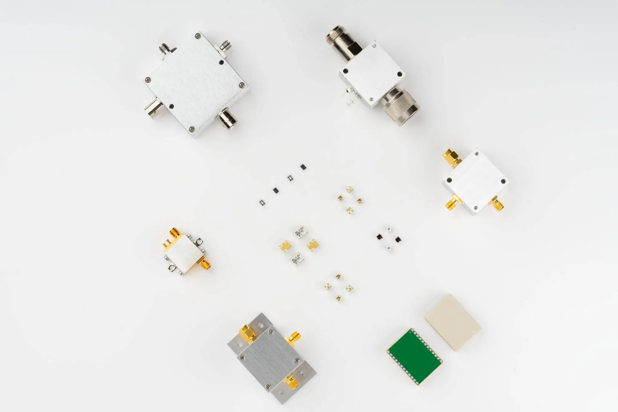
Mini-Circuits offers bias tees in several mechanical configurations for PCB-level integration, laboratory use and complete RF systems.
Surface-mount bias tees are designed for integration directly onto RF and microwave circuit boards.
They are well suited to applications requiring:
Mini-Circuits offers surface-mount bias tees covering RF, microwave and millimeter-wave frequency ranges, with models extending into tens of GHz.
Important selection parameters include frequency range, DC current, insertion loss, isolation, VSWR and PCB layout requirements.
Connectorized or coaxial bias tees provide a convenient solution for laboratory, test, system and field applications where direct RF connector interfaces are required.
Available configurations include several RF connector families depending on model and frequency range.
Coaxial bias tees are particularly useful for:
Selected Mini-Circuits coaxial bias tees operate at frequencies as high as 54 GHz.
Some applications require significant DC current to be delivered through the RF transmission line.
Mini-Circuits offers high-current bias-tee solutions for applications such as:
Selected Mini-Circuits coaxial bias tees support DC current up to 7 A, depending on the individual model.
Always verify maximum DC current, voltage, RF power and thermal limitations in the individual product datasheet.
For high-frequency test and system applications, Mini-Circuits offers bias tees extending into the millimeter-wave range.
Selected models operate up to 54 GHz and use precision high-frequency coaxial interfaces.
These products are suited to applications including:
At these frequencies, insertion loss, return loss, isolation and connector selection become particularly important.
Plug-in bias tees provide a compact through-hole option for PCB integration.
They can be useful where surface-mount assembly is not preferred or where the design requires a mechanically robust PCB-mounted component.
Review frequency coverage, current capability, insertion loss and isolation when selecting a plug-in model.
Mini-Circuits also offers selected bias tees in MMIC die format for chip-and-wire and highly integrated microwave designs.
Bare-die components are particularly useful where:
A bias tee can be considered a specialized form of diplexing network because it separates two different spectral regions: DC or very low frequency and the RF/microwave signal.
Mini-Circuits also offers related diplexer products in which low-frequency and high-frequency RF bands are separated rather than simply separating DC from RF.
For this reason, the MCDI catalog includes both bias-tee and selected diplexer configurations.
When selecting a product, confirm whether your application requires:
For conventional DC biasing of an RF component, a bias tee is normally the appropriate product category.
Choosing the correct bias tee requires balancing the RF requirements of the signal path with the DC requirements of the device being powered.
The bias tee must support the complete RF bandwidth required by your application.
Check both:
The lower cutoff can be particularly important in broadband applications because bias-tee performance depends on the internal DC-blocking and RF-choke network.
Always verify performance across your actual operating band rather than considering only the maximum frequency.
The bias tee must safely carry the DC current required by the powered device.
Applications such as low-noise amplifier biasing may require relatively little current, while remote amplifiers, satellite equipment and other active systems may require considerably more.
Selected Mini-Circuits bias tees support currents up to several amps, with specific high-current models reaching 7 A.
Never exceed the current rating specified in the product datasheet.
Check the maximum permitted DC voltage as well as current.
A model that supports sufficient current may not necessarily support the required DC voltage.
Both parameters need to be compatible with the device being powered.
Insertion loss describes the RF signal loss between the RF port and the combined RF + DC port.
Lower insertion loss is generally desirable because it minimizes degradation of the RF signal.
Insertion loss becomes especially important in:
Check insertion loss across the complete operating-frequency range.
Isolation indicates how effectively the RF signal is prevented from appearing at the DC port.
Good RF-to-DC isolation helps prevent RF energy from entering the power-supply circuitry and potentially affecting system performance.
Isolation should be evaluated across the required RF band.
The bias tee forms part of the RF transmission path, so impedance matching is important.
Poor matching can produce reflections and degrade the performance of the complete system.
Review the specified VSWR or return loss at the RF ports throughout your operating frequency range.
Some applications may expose the bias tee to significant RF power.
Check the permitted RF input power as well as:
Most RF and microwave systems use 50Ω, while selected applications use 75Ω.
Choose a bias tee with impedance matching the rest of the RF signal chain.
Connectorized bias tees are available with different RF interfaces depending on operating frequency and model.
Connector selection may include interfaces such as:
Ensure that both the connector interface and connector gender are suitable for your equipment and cabling.
Choose a mechanical format suited to the final application:
For PCB-mounted products, always follow the manufacturer’s recommended PCB layout and grounding guidance.
Bias tees are used wherever DC power and an RF signal need to share the same transmission line.
One of the most common bias-tee applications is supplying DC power to an RF amplifier while allowing the RF signal to pass through the same connection.
This is particularly useful in laboratory test setups where the amplifier does not include its own integrated bias network.
A bias tee can provide DC power to an active antenna or antenna-mounted amplifier through the RF coaxial cable.
This avoids the need for a separate power cable to the antenna location.
Satellite systems commonly carry both RF or IF signals and DC power through the same coaxial cable.
Bias tees can therefore be used to power equipment such as:
while maintaining the RF signal path.
Bias tees are widely used in RF laboratories to apply DC bias to a device under test while measuring RF performance.
Applications include testing:
High-frequency bias tees can inject DC bias into RF devices while preserving broadband millimeter-wave signal paths.
Selected Mini-Circuits models support applications through 54 GHz.
Bias tees can be used in applications where a DC operating point and a high-frequency modulation signal need to be applied to the same device, including selected optical and laser-diode systems.
Connectorized bias tees make it easy to add or remove DC bias in experimental RF setups without designing a dedicated bias network for every measurement.

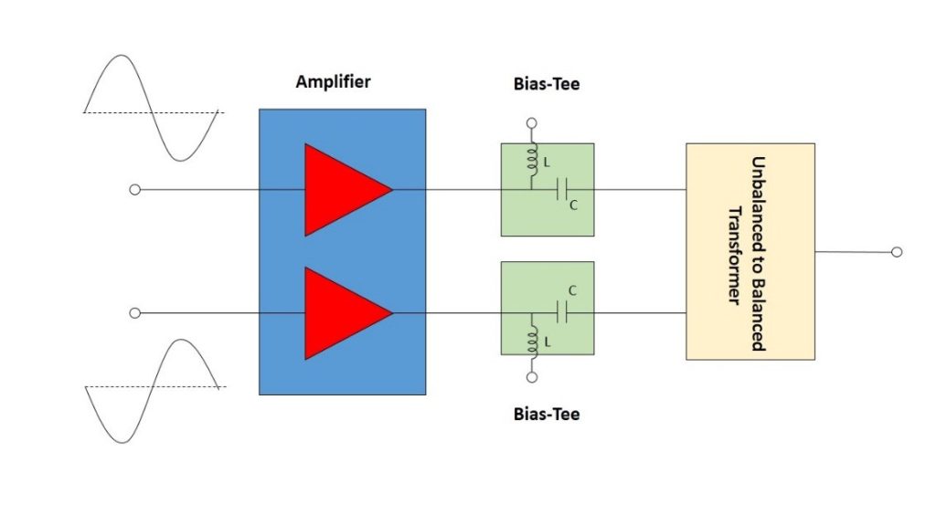
An RF bias tee is a three-port component that allows DC power and an RF signal to share the same transmission line.
It normally has an RF port, a DC port and a combined RF + DC port.
An RF bias tee is a three-port component that allows DC power and an RF signal to share the same transmission line.
It normally has an RF port, a DC port and a combined RF + DC port.
The name refers to its three-port configuration. One path carries the RF signal, one introduces or extracts the DC bias, and the third carries the combined RF and DC signals.
A bias tee is commonly used to supply DC power to an active RF device through the same coaxial cable carrying the RF signal.
Applications include amplifiers, active antennas, LNBs, remote RF modules, test equipment and selected optical devices.
Normally, the RF-only port is DC blocked.
DC is introduced through the DC port and appears at the combined RF + DC port.
Always verify the port configuration in the individual product datasheet.
A bias tee is designed to isolate the DC port from the RF signal.
However, isolation is finite rather than infinite, so the specified DC-port isolation should be checked for the required frequency range.
Insertion loss is the RF signal loss introduced by the bias tee between the RF and RF + DC ports.
Lower insertion loss generally means less degradation of the RF signal.
A bias tee uses frequency-selective elements to separate RF and DC.
The internal components therefore determine how low in frequency the RF path can operate while maintaining acceptable insertion loss, isolation and impedance matching.
Current capability depends on the model.
Mini-Circuits offers bias tees ranging from low-current devices for PCB-level applications to high-current coaxial models, with selected products supporting DC current up to 7 A.
Always verify the individual product’s absolute maximum current and operating conditions.
Both use frequency-selective networks to separate signals.
A bias tee is specifically designed to combine or separate DC and RF on the same transmission line. A conventional RF diplexer normally separates two different RF frequency bands.
Yes. Applying DC bias to an RF amplifier through its RF connection is one of the most common uses for a bias tee.
The bias tee must be selected to support the amplifier’s RF frequency range, DC voltage and current requirements.
Yes, provided the bias tee’s voltage, current, frequency and impedance specifications are compatible with the active antenna system.
Yes. Selected Mini-Circuits coaxial bias tees operate through 54 GHz, making them suitable for high-frequency and millimeter-wave test and system applications.
Yes. MCDI’s Application Engineering team in Israel can help identify appropriate Mini-Circuits bias tees according to your RF frequency range, voltage, current, power, insertion loss, isolation, impedance and mechanical requirements.
MCDI is Mini-Circuits’ exclusive representative and distributor in Israel, providing Israeli engineers and purchasing teams with access to Mini-Circuits RF, microwave and millimeter-wave products together with local technical, commercial and logistical support.
Selecting the correct bias tee may require balancing RF bandwidth, DC current, voltage, insertion loss, isolation, VSWR, power and interface requirements.
MCDI’s Application Engineers can help evaluate those requirements and identify suitable Mini-Circuits models.
Discuss your application directly with an Israel-based engineering team familiar with Mini-Circuits RF components and systems.
If you know your operating frequency, DC voltage and current but are unsure which bias tee to use, send MCDI your requirements and our team can help identify appropriate options.
MCDI supports customers in Israel from product selection and quotation through ordering, logistics and post-sales technical assistance.




Before you leave, you should know that MCDI’s professional team of Application Engineers will be delighted to assist you in sourcing the right component. Just fill the form and we will be back to you shortly.