Compensating Frequency-Dependent Cable Loss in CATV Systems with Mini-Circuits Voltage-Variable Equalizers
Ben Kahtan, Applications Engineer, Mini-Circuits
In broadband communications systems such as CATV equipment, system performance may critically rely on gain or attenuation flatness. In particular, CATV systems are often plagued by issues resulting from the frequency-dependent attenuation of very long cables (increasing with frequency) as well as the negative gain slope of certain amplifiers. This negative gain slope exhibited by CATV system components can cause a variety of headaches for system designers.
For example, suppose the system’s operating bandwidth is split into a number of channels. Channels at lower frequencies are subject to much less attenuation than those at higher frequencies, so the “louder” low-frequency channels may saturate an amplifier exhibiting sufficient gain to amplify the “quieter” high-frequency channels. Obviously an amplifier driven to saturation in a spectrally rich multi-channel system would result in a whole mess of impossible-to-filter-out intermodulation products, so this situation is highly undesirable.
Out-of-band spurious spectral content (e.g. intermodulation products, harmonics) from the louder lower-frequency signals may also degrade the quality of the quieter, higher-frequency signals (be it in terms of MER, SNR, CNR, or any other Figure-Of-Merit flavors) – and so on.
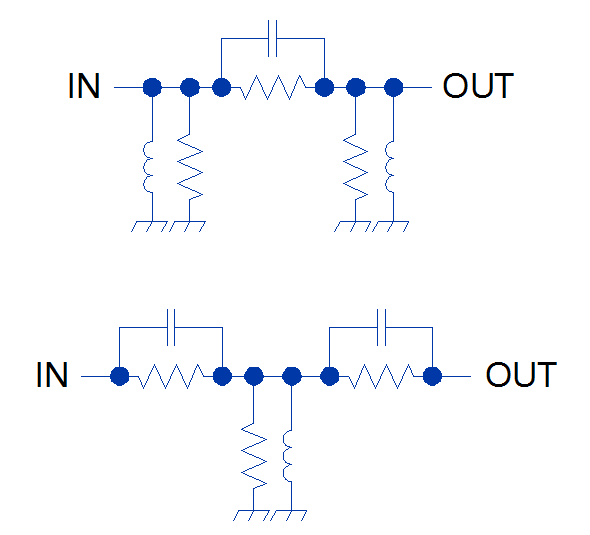
Because both the amplifiers and the cables exhibit a negative gain/attenuation slope, in many cases a designer may wish to flatten this slope at the expense of overall gain. This can be done with a device that has a positive attenuation slope (over the desired operating frequency range), called an equalizer. Equalizers may be realized, for example, as resistive pi or tee networks with the series resistive elements “bypassed” by parallel capacitors and the shunt resistive elements “bypassed” by parallel inductors, effectively forming a lossy low-order high-pass structure. Figure 1 illustrates this concept.
Passive equalizers are relatively simple to design, and inexpensive to implement, but they lack versatility due to passive component values being fixed.
Any designer worth his salt will know that component performance varies with temperature, manufacturing tolerances, humidity, the installation technician’s choice of breakfast on the preceding Tuesday, and so on. So, an equalizer that exhibits an attenuation slope for 300 feet of Manufacturer A’s coaxial cable, roasting at high noon during a Texan summer, might not work so well with 50 icicle-draped feet of Manufacturer B’s cable in Maine. A designer may choose to design into her or his system a switchable bank of equalizers, which may be inserted into the signal path as necessary, but a discretized solution like this can rapidly turn cumbersome.
Because the “amount” of positive slope needed to effectively flatten the gain of a particular system will vary depending on cable length, amplifier performance, gain/attenuation variations thereof over temperature, and myriad other system parameters, passive equalizers are applicable to relatively narrow regimes of operating conditions. A tunable solution, on the other hand, would be highly desirable.
Mini-Circuits’ VAEQ-1220-75+ offers exactly that—an equalizer whose attenuation slope is adjustable via an analog control signal. This component offers significantly increased versatility under the widely-varied operating conditions to which CATV systems are subjected. An “intelligent” control system can tune the voltage-variable equalizer’s (VVE) frequency response on the fly, continually adapting to changes in operating parameters, and maintaining peak system performance.
Figures 2 and 3 illustrate the performance of a simplified hypothetical CATV system (consisting of two Mini-Circuits PGA-106-75+ amplifiers and 100 feet of RG-6/U coaxial cable). The red plot shows the gain of this system without the equalizer, and the blue plot shows the gain of this system with Mini-Circuits’ VAEQ-1220-75+ voltage-variable equalizer inserted. In this simulation, a tuning voltage of 3.05 volts is applied to the VVE through its control input.

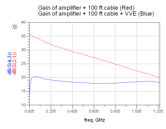
In this hypothetical system, the VAEQ-1220-75+ reduces a slope of about -20 dB to a nearly flat region. While this model has a particularly flat response within the DOCSIS 3.1 downstream band—up to 1220 GHz (and change)—it is also operable down to 5 MHz.
The VAEQ-1220-75+ is designed for use in 75Ω systems and is operable over the entire DOCSIS 3.1 bandwidth—both upstream and downstream frequencies—making it an ideal solution for the needs of the CATV world. S-parameter models at several control voltage states are available for this part, and Mini-Circuits can make additional data available on request to help you design the VAEQ-1220-75+ into your CATV systems.
In addition, if the VAEQ-1220-75+ isn’t entirely suitable for your system, Mini-Circuits can assist in developing a special voltage-variable equalizer model to meet your exact needs, whatever they may be.


