

Wideband Connectorized Amplifiers for mmWave Over-The-Air (OTA) Transmitter & Receiver Testing
Anirudh Venkatesan, Mini-Circuits Engineering
The advent of 5G networks has already begun ushering in a whole new generation of wireless devices and applications, and device manufacturers are racing to be the first market. In order to meet the 5G standard for commercial wireless communication, device manufacturers need to develop powerful transmitters and receivers that operate in the millimeter wave range, which comes with a number of challenges, one of which is testing and qualification. Due to the wireless nature of these devices, manufactures need to conduct testing in real-world conditions, which isn’t possible using the conventional approach of connecting devices under test (DUTs) to instruments with coaxial cables. Over-the-air (OTA) allows engineers to more realistically simulate real-world device performance in the lab environment.
OTA testing uses antennas to transmit and receive RF channel power instead of cables. It is often conducted in anechoic chambers where designers can introduce different conditions such as interfering signals and monitor any effects on performance. Since most communication devices include both transmit and receive capabilities, both the transmit power and receive sensitivity need to be tested. Each path requires a different setup, but both cases require the use of suitable wideband amplifier either to drive power to the antenna on the transmit side or to amplify small signals on the receive side.
This article will briefly describe common test setups for OTA testing of transmit and receive signal chains and illustrate uses for Mini-Circuits’ ultra-wideband connectorized amplifiers within these setups. Note that in this article, we will be considering a cell phone as the DUT for illustration, but the same tests are applicable for other wireless devices as well.
Total Radiated Power (TRP)
Total Radiated Power (TRP) testing measures the total power radiated by a transmitter in a cell phone or other device in a given RF channel. This includes testing how much power is delivered to the cell phone’s antenna by the RF power amplifier in the transmitter chain, and how good the antenna is at converting this RF power into radiated power. A typical TRP setup is shown figure 1.
 Transmitter & Receiver Testing 1")
One such amplifier used by Mini-Circuits customers in OTA testing is the ZVA-24443G1+. This model is used for testing in the 5G FR2 bands from 24 GHz to 40 GHz. The amplifier operates from 24 to 43.5 GHz. It has a nominal gain of 45 dB with gain flatness of ±3 dB and a low noise figure of around 1.7 dB. Other amplifiers also suitable for TRP testing in the 5G FR2 bands are shown below in table 1.
| Model No. | Freq. Range (GHz) | Gain (dB) | Gain Flatness (dB) | Noise Figure (dB) |
| ZVA-24443G1+ | 24 – 43.5 | 45 | ±3 | 1.7 |
| ZVA-18403G+ | 18-40 | 43 | ±1.2 | 3.8 |
Table 1: Wideband LNAs suitable for high-frequency TRP testing
Total Isotropic Sensitivity (TIS)
The purpose of Total Isotropic Sensitivity (TIS) testing is to measure the cell phone antenna’s ability to receive low power signals. This is an iterative process that involves measuring the power received by the cell phone in a given RF channel. The measurement involves incrementally reducing the power of transmitted the setup transmitter antenna and measuring the bit error rate (BER) at the cell phone. Once a specified maximum BER is reached, the corresponding received power is recorded as the sensitivity. A typical TRP set up is shown figure 2. for high-frequency TIS testing
 Transmitter & Receiver Testing 2")
The transmit antenna of the setup transmits the power to the cell phone’s antenna. This power is boosted by an amplifier to compensate for the path loss such that useable power is received at the cell phone’s antenna. In this case, the amplifier in the setup acts as a typical power amplifier in a transmit chain. Therefore, it needs to have a sufficient output power for an accurate measurement. For 5G OTA measurements, these power amplifiers need to have a relatively high output power at a high frequency up to 40 GHz.
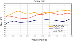
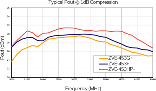
Mini-Circuits’ ZVA-24443G1+ discussed above has also proved useful in TIS testing, with an output power at 1dB compression (P1dB) of +23 dBm. For higher output power with even wider frequency coverage, Mini-Circuits’ new ZVE-453+ series of ultra-wideband amplifiers are ideal for TIS testing setups. Specs for these models are summarized in Table 2 below. Performance curves for gain and output power are shown in Figure 3. All models in the ZVE-453+ series operate on a single, positive supply voltage from 10 to 15V and feature internal voltage regulation and sequencing as well as built-in over-voltage and reverse voltage protection. They’re available from stock with and without a heatsink and 2.92 mm RF connectors. An optional PSAT control pin and 2.92 mm connectors are also available on request.
| Model No. | Freq. Range (GHz) | Gain (dB) | Gain Flatness (dB) | P1dB (dBm) |
| ZVA-24443G1+ | 24 – 43.5 | 45 | ±3 | 23 |
| ZVE-453+ | 18-45 | 33 | ±2.5 | 29 |
| ZVE-453G+ | 18-45 | 41 | ±3 | 28 |
| ZVE-453HP+ | 18-45 | 39 | ±2.5 | 31 |
Table 2: Amplifiers suitable for high-frequency TIS testing
Figure 3: Typical gain and output power performance for Mini-Circuits’ ZVE-453+ series of ultra-wideband amplifiers.


