Demystifying RF Transformers: Part 1: A Primer on the Theory, Technologies and Applications
William Yu and Urvashi Sengal, Mini-Circuits, Brooklyn, N.Y.
Introduction
In essence, a transformer is merely two or more conductive paths linked by a mutual magnetic field. When a varying magnetic flux is developed within the core by alternating current passing through one conductive path, a current is then induced in the other conductive paths. This induced current is proportional to the ratio of magnetic coupling between the two conductive paths. The ratio of the magnetic coupling of the conductive paths with the core determines the induced voltage in the additional conductive paths, providing both an impedance transformation and a voltage step-up or step-down. Additional conductive paths, potentially all with different coupling ratios, may be added to realize various functions, which is why RF transformers are such varied and versatile devices used widely throughout the RF/microwave industry.
A common implementation of an RF transformer consists of two or more distinct wires wrapped around a magnetic core (or air core for higher frequencies), which is why RF transformers are often described as a ratio of the number of windings, or turns.
RF transformers are used for a wide variety of applications, as the nature of the device allows for various configurations that can serve a variety of different functions, including (but not limited to):
- Injecting DC current
- Providing DC isolation between circuits
- Enhancing common mode rejection
- Providing an impedance transformation for impedance matching
- Efficiently coupling between balanced and unbalanced circuits
- Inducing a voltage/current step-up or step-down
There are several common technologies used to build transformers, including core-and-wire, transmission line, low temperature co-fired ceramic (LTCC), and monolithic microwave integrated circuit (MMIC). Each comes in a variety of packages and with a wide range of performance characteristics.
This article is the first part in our Demystifying RF Transformers series, and focuses on introducing RF transformer theory with discussion of common RF transformer technologies and applications.
Transformer Theory and Practical Insights
Though not viable for practical applications, the basic Ideal Transformer Model is helpful in illustrating the fundamental behavior of transformers. Consider the diagram, Figure 1.

The current through the primary winding creates a magnetic flux (Faraday’s Law) through the mutual magnetic field of the core, inducing a proportional current and voltage in the secondary winding. Both the current and voltage developed are proportional to the windings ratio, or magnetic coupling between the windings and the core.
Hence, the secondary impedance is a function of the square of the windings ratio times the impedance of the primary (Equation 1). Where I1, V1, and Z1 are the current, voltage, and impedance through the primary winding; I2, V2, and Z2 are the current, voltage, and impedance through the secondary winding, N1 is the number of turns in the primary winding; N2 is the number of turns in the secondary winding; 1 and 2 are the input ports of the primary winding; and lastly, 3 and 4 are the output ports of the secondary winding.

However, a real transformer intrinsically includes several parasitic resistances, inductances, and capacitances, of which there are both mutual and self-parasitic capacitances. Illustrated in Figure 2 is a lumped-element model of a non-ideal transformer, which depicts parasitic resistances and inductances of the two windings, as well as core resistive losses and the windings’ active inductance. It is clear from the model for a non-ideal transformer that these devices operate with a limited bandwidth, have insertion loss, a maximum power rating, and exhibit other frequency-, temperature- and power-dependent performance.

Typically, a real RF transformer’s lower cutoff frequency is dictated by the winding’s active inductance, and the high frequency cutoff is dominated by the inter-winding and intra-winding capacitance. Insertion loss present in the operating bandwidth is a product of the primary and secondary winding ohmic losses, as well as the dissipation within the core. As ohmic losses tend to be a function of frequency and temperature, the effective operating bandwidth of a transformer is limited by these factors. Several RF transformer types also introduce leakage inductances due to incomplete magnetic coupling between the windings. As the leakage inductance’s reactance is proportional to frequency, these parasitics reduce the return loss at high frequencies but increase the insertion loss at lower frequencies.
More complex RF transformer topologies, i.e. transformers with several windings, taps, and additional elements present varying performance dynamics based on the topology and transformer construction. For example, an RF device, known as a Balun, which is used to efficiently interconnect balanced (differential signal path) RF circuits to unbalanced (single-ended signal path) RF circuits using impedance transformation, can be realized with an RF transformer. Moreover, another device similar to a Balun, known as an Unun, which is used to interconnect unbalanced to unbalanced RF circuits, can also be realized with an RF transformer.
A common Balun fashioned from a transformer is a flux coupled Balun Transformer, which is constructed by winding separate wires around a magnetic core and grounding one side of the primary winding. Hence, the single-ended RF signals entering the primary unbalanced winding side undergo an impedance transformation to a differential (balanced) output through the secondary winding. A deeper examination of Balun and Unun theory, functions, and performance will be presented in Part 2 of the Demystifying RF Transformers series.
Notes on Transformer Magnetic Cores
RF transformers that include a magnetic core (typically ferromagnets) are subject to several undesirable performance degrading factors. For instance, the magnetizing inductance of the core limits the low frequency performance of an RF transformer. The magnetizing inductance is a function of the core permeability, cross sectional area of the magnetic core, and the number of windings around the core. The magnetizing inductance increases the insertion loss at low frequencies and also decreases the return loss. Furthermore, the permeability of the core is a function of temperature, for which increases in permeability subsequently increase the low frequency insertion loss.
RF Transformers Technologies
The two main types of discrete RF transformers are core-and-wire and transmission line transformers. Additionally, there are two common types of low-profile and compact RF transformer designs: LTCC and MMIC transformers.
Core-and-Wire RF Transformers
Core-and-wire RF transformers are fabricated by wrapping conductive wires, typically insulated copper wires, around a magnetic core, such as a toroid. There may be one or more secondary windings, which may also be center tapped to enable additional functions. Figure 3 shows an RF transformer made from a toroidal magnetic core and insulated copper windings. Due to the nature of the inductive coupling between the wires and the core, smaller core and wire dimensions tend to yield core-and-wire transformers that can operate at much higher frequencies than larger core-and-wire transformers. However, the smaller dimensions of compact core-and-wire transformers also increase the resistive losses of the windings and the core, which exhibits greater insertion loss at lower frequencies.

Transmission Line RF Transformers
There are a variety of transmission line transformer topologies, which may include precisely designed transmission lines placed between two mismatched loads, or a complex arrangement of several transmission lines. For instance, a length of transmission line can be used to implement an impedance transformation between two mismatched loads. Some transmission line transformers use insulated wires wrapped around ferrite cores, which closely resemble typical core-and-wire transformers, and are often considered core-and-wire transformers. The following explanation is less for categorization purposes, but meant to describe aspects of transformer behavior and enhance understanding.
A basic transmission line transformer consists of a two-conductor transmission line. The first conductor is connected from the generator to the load, and the other conductor is connected at the output of the first transmission line and the load to ground, as seen in Figure 4. With this configuration, the current flowing through the load is twice the current flowing through the generator, and V0 is one half the voltage V1. Hence, the load resistance is only a quarter of the resistance seen at the generator side, yielding a 1:4 transformer (Equation 2).


A common transmission line transformer variation is the quarter-wave transmission line transformer. This topology uses a transmission line with a characteristic impedance that enables impedance matching between the input impedance and the load. The length of a quarter-wave transformer is dictated by the desired frequency of operation, and is limited to one bandwidth octave around the center frequency. Consider a lossless transmission line with Z0 characteristic impedance and length L, connected between Zin input impedance and ZL load impedance as seen in Figure 5. In order to match Zin with ZL, the characteristic impedance of the quarter-wave transmission line would need to be the square root of Zin multiplied by ZL (Equation 3).


An advantage of a transmission line transformer is that a significant portion of the interwinding capacitance is assumed by the transmission line parameters, along with the leakage inductance, which results in a comparatively wider operating bandwidth compared to core-and-wire transformers.
LTCC Transformers
Low Temperature Co-fired Ceramic (LTCC) components are multilayer components that are fabricated using a ceramic-based substrate. LTCC transformers use coupled lines that act as transmission lines in order to achieve impedance transformation and signal conversion from single-ended to balanced. LTCC transformers rely on capacitive coupling to operate. This allows LTCC transformers to operate at higher frequencies compared to ferromagnetic transformers, but may lead to performance degradation at low frequencies. The benefit of LTCC technology is the ability to fabricate small and rugged transformers ideal for hi-rel applications, as seen in Figure 6.

MMIC Transformers
Like LTCC technologies, MMIC transformers are made using high-precision layered 2D substrates with planar metallization. Typically, MMIC transformers are fabricated using spiral inductors printed on a substrate in a two transmission line configuration parallel to each other. The MMIC process is helpful for producing high frequency transformers, and exhibits outstanding repeatability and excellent thermal efficiency. A MMIC transformer can be fabricated using gallium arsenide (GaAs) integrated passive device (IPD) process, as seen in Figure 7.

Introduction to RF Transformer Functions & Applications
As indicated in previous sections of this article, there are a variety of functions that RF transformers can perform depending upon their typology.
Transformation Functions
For instance, an impedance transformation function can be used to match two circuits with disparate impedance, or also provide a voltage step-up or step-down respective to a source voltage.
Impedance Matching Transformers
There are many cases in RF circuits where a mismatch in impedances between two nodes can cause reduced power transfer efficiency and potentially troublesome reflections. Hence, an impedance matching transformer can be used to effectively eliminate the reflections and provide maximum power transfer between the two circuit nodes (see Figure 8).

Ununs and Baluns
Moreover, for unbalanced lines, an autotransformer configuration can be used for impedance matching, i.e. an Unun. As mentioned earlier, Balun transformers can also be used to interconnect balanced and unbalanced circuit sections.
DC Isolation
An RF transformer can also be designed to provide DC isolation between the primary and secondary windings, which can be useful for separating RF circuits that require a DC bias on the RF transmission line from RF circuits that would be negatively impacted by a DC voltage on the signal line.
Injecting DC Current
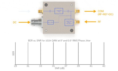
Moreover, if a DC current is required for a subsection of a circuit, a specialized RF transformer can be used to inject DC current into the signal path. For example, two center tapped transformers can be used to inject a DC bias, replacing the need for two Bias Ts (see Figure 9).

Enhancing Common Mode Rejection
Certain RF transformer designs can be used to provide enhanced common mode rejection (CMR) for balanced (differential) circuits.
RF Choke
Other topologies can be used to filter high frequency RF components from a signal line, functioning as a choke.
Conclusion
RF transformers can be fabricated with a wide variety of manufacturing methods, with a diverse range of materials, and can be configured into a myriad of topologies in order to perform useful functions for RF circuits. Depending on the materials, construction, and design, RF transformers can be narrow- or wide-band, and operate at low RF frequencies or high. Understanding the basics, as well as more detailed nuances, of RF transformers can help a designer optimize a design with the right transformer selection.
This concludes Part 1 of the Demystifying RF Transformers Series. Stay tuned for the following articles:
- Demystifing RF Transformers Part 2: Baluns & Ununs
- Demystifing RF Transformers Part 3: Understanding RF Transformer Performance Parameters
- Demystifing RF Transformers Part 4: How to Select the Ideal Transformer
Resources
- https://www.minicircuits.com/app/AN20-001.pdf
- https://www.minicircuits.com/app/AN20-002.pdf
- https://www.minicircuits.com/appdoc/TRAN14-2.html
- RF and Microwave Transformer Fundamentals featured in Microwave Products Digest 10-2009
- https://www.mcdi-ltd.com/rf-transformers-and-baluns/


