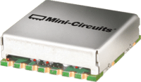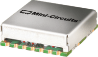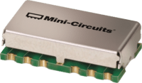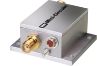

MCDI offers a selection of Mini-Circuits RF voltage-variable phase shifters for precise analog phase control in RF, IF and microwave signal chains.
The portfolio includes 180° and 360° continuous phase-control models in compact surface-mount and rugged connectorized configurations, with standard catalog products covering applications from low-frequency RF through 2.484 GHz.
Selected special or non-catalog Mini-Circuits phase-shifter models extend to frequencies as low as 1.8 MHz.
Mini-Circuits phase shifters are used in applications including:
Important selection parameters include:
MCDI’s Application Engineering team in Israel can assist you in selecting the appropriate Mini-Circuits phase shifter according to frequency, phase-control range, insertion-loss budget, tuning speed, RF power and mechanical requirements.
Hebrew & English Professional Support
Get a quote within hours or less
DDP & Ex-Works - your choice
Custom Adapters & Catalog modifications
Access to Mini-Circuits full portfolio
Mini-Circuits Quality & Reliability
Use the RF Phase Shifter Catalog below to search and compare Mini-Circuits products according to your application requirements.
For complete phase-versus-voltage, insertion-loss, VSWR, RF power, control-input, temperature and absolute-maximum specifications, always review the individual Mini-Circuits product datasheet.
Surface-Mount – 180° Voltage Variable
Compare according to:
Compare according to:
Compare according to:
An RF phase shifter changes the phase of an RF signal while ideally maintaining its amplitude and frequency.
The amount of phase shift is normally expressed in:
Degrees – °
A voltage-variable phase shifter uses an analog control voltage to continuously adjust phase over a specified range.
Mini-Circuits offers devices providing up to:
depending on model.
Unlike a phase detector, which measures phase difference, a phase shifter actively changes the phase of the RF signal.
Phase is fundamental to the way RF signals combine.
Two signals at the same frequency can:
depending on their relative phase.
Controlling phase is therefore important in applications such as:
A 180° phase shifter provides continuous analog phase adjustment over at least approximately half of a complete RF cycle.
Mini-Circuits surface-mount 180° products cover a wide range of RF and IF applications.
Typical uses include:
Available models provide control-voltage ranges such as:
depending on device.
The required phase is selected by applying the corresponding control voltage.
A 360° phase shifter provides approximately one complete cycle of continuous phase adjustment.
This is useful when any desired relative phase within a full cycle may be required.
Applications include:
Mini-Circuits offers 360° surface-mount models from low-frequency RF through approximately 1.5 GHz, plus a connectorized SMA solution covering 250 to 430 MHz.
Surface-mount phase shifters provide compact phase-control functionality for PCB-level integration.
Benefits include:
Mini-Circuits offers both 180° and 360° surface-mount architectures.
Typical applications include:
Coaxial phase shifters are convenient for laboratory, system and prototype applications because they can be inserted directly into a coaxial RF path.
The current Mini-Circuits ZXPHS-431-S+ provides:
Connectorized phase shifters are useful in:
A voltage-variable phase shifter provides a control port in addition to the RF input and output.
Changing the control voltage changes the internal reactance or delay characteristics of the device and therefore changes the phase of the RF signal.
Conceptually:
Control Voltage → Phase Shift
However, the relationship is not necessarily perfectly linear.
For example, applying half of the maximum control voltage does not automatically produce exactly half of the maximum phase range.
Always use the individual product’s:
when accurate phase settings are required.
Phase range indicates the minimum total amount of phase adjustment available over the specified control-voltage range.
For example:
180° minimum phase range
means the device provides at least 180° of available phase adjustment under its specified conditions.
It does not mean:
Actual phase-versus-voltage behavior varies with frequency and model.
These are different concepts.
The total amount of available phase adjustment.
Example:
360° minimum
How closely an actual commanded phase matches the desired phase.
The Mini-Circuits analog phase shifters on this page are primarily specified by available phase range, together with measured phase-versus-voltage performance.
For applications requiring precise calibrated phase values, the control voltage may need to be determined from measured or datasheet tuning curves.
A phase shifter introduces some RF signal loss.
Insertion loss is normally specified in dB.
Lower insertion loss is generally desirable, especially in:
However, insertion loss can vary with:
The complete performance curves should therefore be reviewed for precision applications.
An ideal phase shifter would change only phase while leaving signal amplitude completely unchanged.
Real phase shifters may show some insertion-loss variation as the control voltage changes.
This means different phase settings may produce slightly different output amplitudes.
In applications such as phased arrays or coherent combining, both:
may affect system performance.
System calibration can compensate for some of these effects.
The control-voltage range determines the analog voltage required to tune through the phase range.
Current Mini-Circuits products use ranges including:
depending on model.
The control source should provide:
Noise on the control voltage can produce unwanted phase modulation.
Control bandwidth indicates how rapidly the phase shifter can respond to changes in its control voltage.
Current Mini-Circuits analog phase shifters commonly specify typical control bandwidths such as:
depending on model.
A phase shifter specified as:
DC–50 kHz control bandwidth
can respond to static control voltage as well as changing control signals within its specified analog control bandwidth.
Control bandwidth may be important for:
A phase shifter is inserted directly into the RF transmission path, so impedance matching is important.
Poor VSWR can create:
Mini-Circuits specifies typical and maximum VSWR across the operating range for each model.
Review VSWR across the actual frequencies and phase settings required by the application.
Phase shifters have both operating-power recommendations and absolute maximum ratings.
These values are not necessarily the same.
For example, a datasheet may specify an absolute maximum RF input higher than the recommended maximum RF power for normal phase-shifter operation.
The absolute maximum rating identifies a damage threshold and should not be treated as the recommended continuous operating level.
Always check the individual product datasheet for:
The phase shifter must provide the required phase range, insertion loss and VSWR throughout the actual operating band.
Mini-Circuits standard catalog products extend through 2.484 GHz, with selected non-catalog solutions available at lower frequencies.
Choose:
180°
when half-cycle phase adjustment is sufficient.
Choose:
360°
when the application requires access to essentially any phase within a complete cycle.
Analog voltage-variable phase shifters do not have fixed digital phase steps.
Resolution is determined by:
For systems requiring very fine adjustment, consider the complete voltage-control chain.
Include phase-shifter insertion loss in the overall RF link budget.
This is especially important when the device is placed before:
Make sure the control electronics can generate the full required tuning range.
If digital control is required, a DAC can generate the analog control voltage.
For static calibration, control bandwidth may be relatively unimportant.
For dynamic beam steering, tracking or modulation, verify that the phase shifter’s control bandwidth supports the required update rate.
Select a phase shifter with suitable impedance matching over both:
to minimize signal reflections.
Verify the normal operating power and absolute maximum rating separately.
Do not design continuous operation at the absolute maximum rating.
Choose surface mount for:
Choose connectorized for:
A phased-array antenna controls beam direction by adjusting the relative phase of the signal feeding each antenna element or group of elements.
Changing these relative phases changes how the radiated signals combine in space.
This enables:
without mechanically rotating the antenna.
Phase shifters are therefore fundamental components in many:
Phase accuracy, insertion-loss variation and cable phase matching all contribute to final array performance.
A phase shifter controls electrical phase intentionally.
Cables also introduce phase delay because every cable has an electrical length.
In multi-channel systems such as phased arrays, cable-to-cable electrical-length variation can therefore consume part of the available phase-correction range.
Using phase-matched RF cable assemblies can reduce the amount of correction required from each phase shifter and simplify system calibration.
A phase shifter and phase detector perform opposite roles.
Changes the phase of an RF signal.
Input: RF signal + control voltage
Output: RF signal with adjusted phase
Measures the relative phase between two RF signals.
Input: Two RF signals
Output: DC voltage related to phase difference
The two components can be used together in a closed-loop phase-control system:
Reference → Phase Detector → Control Circuit → Phase Shifter
A phase shifter controls signal phase over a specified frequency band.
A delay line introduces a defined time delay.
The distinction is important because:
Phase = 360° × Frequency × Delay
Therefore, a fixed time delay corresponds to different phase shifts at different frequencies.
A phase shifter optimized for a particular band may therefore behave differently from a true time-delay element in a wideband phased-array application.
A phase detector and voltage-variable phase shifter can be combined to create an automatic phase-alignment loop.
For example:
Reference Signal
→ Phase Detector
→ Loop / Control Electronics
→ Phase Shifter
→ Controlled RF Path
The loop can continuously adjust the phase shifter to maintain the required relationship between two RF signals.
Potential applications include:
Mini-Circuits also maintains selected phase-shifter models outside the standard catalog.
For example, JCPHS-2.5+ provides:
but is currently identified by Mini-Circuits as a non-catalog model.
If your requirement falls outside the standard MCDI table, contact our Application Engineering team to check availability of:
Control the relative phase of antenna-element signals for electronic beam steering and array calibration.
Phase shifters can support:
Voltage-variable phase control can be used in:
Connectorized and surface-mount phase shifters can be used to introduce controlled phase changes during:
When two coherent RF paths are combined, their relative phase affects the combined output power.
A phase shifter can be used to align the signals for constructive combination.
Conversely, controlling relative phase can produce destructive interference for:
Low-frequency phase shifters can be useful in IF signal-processing systems requiring controlled analog phase adjustment.
An RF phase shifter is a component that changes the phase of an RF signal while ideally leaving its frequency and amplitude unchanged.
A voltage-variable phase shifter uses an analog control voltage to continuously change RF phase over a specified range.
Mini-Circuits currently offers standard analog phase-shifter models with minimum phase-control ranges of approximately 180° and 360°.
Current standard products extend through 2.484 GHz.
Mini-Circuits also lists selected non-catalog products extending down to approximately 1.8 MHz.
Always verify current catalog and availability status for the individual model.
A 180° model provides approximately half a full RF cycle of available phase adjustment.
A 360° model provides approximately one full cycle, allowing access to essentially any relative phase over 0–360°.
No.
Phase range indicates the amount of phase adjustment available.
It does not specify phase accuracy.
Not necessarily.
The relationship between phase shift and control voltage varies with model and frequency.
Use the product’s measured phase-versus-voltage data for accurate control.
Insertion loss is the RF signal power lost when the phase shifter is inserted into the signal path.
It may vary somewhat with phase setting and frequency.
Control bandwidth indicates how quickly the phase shifter can respond to changes in control voltage.
Current Mini-Circuits products commonly specify analog control bandwidths such as DC–30 kHz or DC–50 kHz.
The devices on this page are analog voltage-variable phase shifters.
They can be controlled from a digital system by using a suitable DAC to generate the analog tuning voltage.
A phase shifter changes RF phase.
A phase detector measures phase difference between two RF signals and produces an electrical output related to that difference.
Yes.
A phase detector, controller and voltage-variable phase shifter can form a closed-loop phase-control system.
Yes.
Phase shifters are fundamental components in many phased-array systems because controlling relative phase between antenna elements allows electronic beam steering.
Cable electrical length also contributes phase shift.
Large cable-to-cable phase differences can consume available phase-shifter correction range and complicate array calibration.
A phase shifter controls phase over a specified frequency range.
A delay line introduces time delay.
Because phase depends on both delay and frequency, a fixed time delay produces different phase shifts at different frequencies.
RF power capability depends on model.
Be careful to distinguish normal operating-power limits from absolute maximum input-power ratings.
Always use the individual datasheet.
Yes.
Mini-Circuits offers a connectorized 360° voltage-variable phase shifter using SMA interfaces for selected frequencies.
Yes.
Selected phase-shifter models are maintained as non-catalog products, and MCDI can help evaluate availability for applications outside the standard catalog.
Yes.
MCDI’s Application Engineering team in Israel can help identify appropriate Mini-Circuits phase shifters according to frequency, phase range, insertion loss, control voltage, control bandwidth, RF power and mechanical requirements.
MCDI is Mini-Circuits’ exclusive representative and distributor in Israel, providing Israeli engineers and purchasing teams with access to Mini-Circuits RF products together with local technical, commercial and logistical support.
Local Application Engineering
Phase-shifter selection requires balancing:
MCDI’s Application Engineers can help identify suitable Mini-Circuits products.
Technical Support in Hebrew and English
Discuss your phase-control or beamforming requirements directly with an Israel-based engineering team familiar with Mini-Circuits RF components.
Complete Phase-Control Support
MCDI can also assist with related Mini-Circuits products including:
allowing the phase shifter to be evaluated within the complete RF system.
Phased-Array Support
For phased-array applications, MCDI can assist with phase-control components together with phase-matched cables, splitters, amplifiers and related RF components.
Special & Custom Solutions
If the standard catalog does not provide the required phase range, frequency or mechanical format, MCDI can help evaluate Mini-Circuits special and non-catalog solutions.
Support from Selection Through Delivery
MCDI supports customers in Israel from product selection and quotation through ordering, logistics and post-sales technical assistance.




Before you leave, you should know that MCDI’s professional team of Application Engineers will be delighted to assist you in sourcing the right component. Just fill the form and we will be back to you shortly.