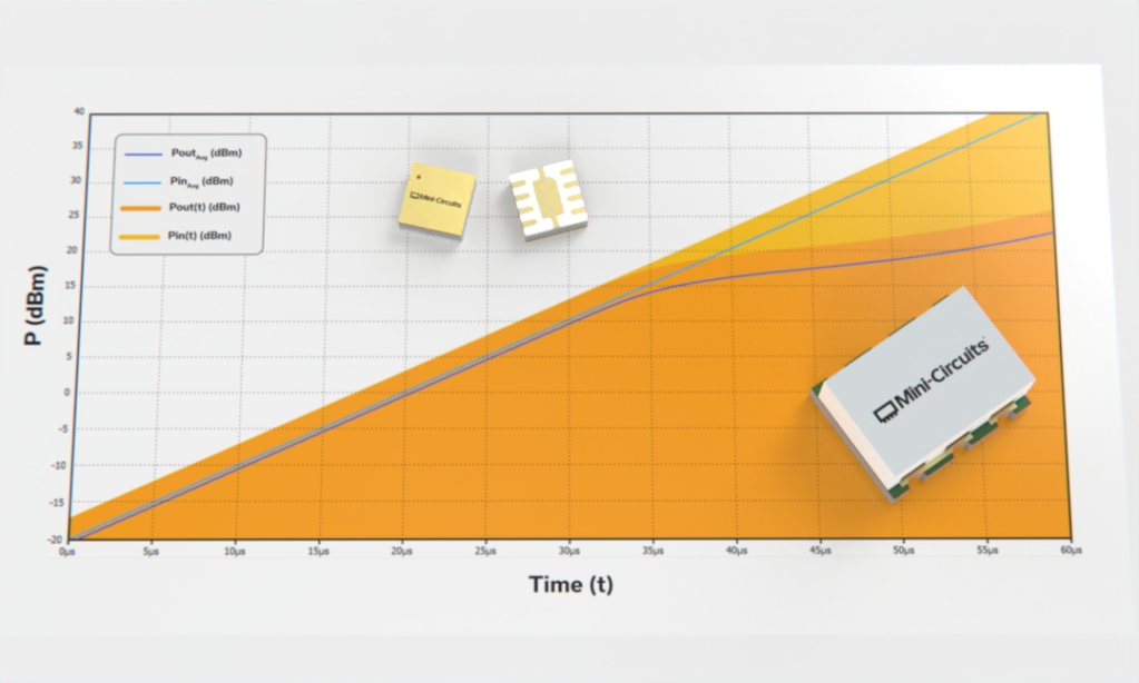

MCDI offers a selection of Mini-Circuits RF and microwave limiters designed to protect sensitive RF components from excessive input power, unwanted high-level signals and RF power surges while allowing normal low-level signals to pass with low insertion loss.
The portfolio includes surface-mount, coaxial and plug-in RF limiters, with selected models covering frequencies from 100 kHz to 8.2 GHz.
Mini-Circuits limiters are used in receiver front ends, RF test systems, radar, communications equipment and other applications where sensitive components such as low-noise amplifiers, mixers and measurement circuitry may be exposed to unexpectedly high RF power.
Important limiter specifications include operating frequency, small-signal insertion loss, limiting input range, limited output or leakage power, limiting slope, recovery time, RF power rating and mechanical format.
MCDI’s Application Engineering team in Israel can assist you in selecting the appropriate limiter according to your frequency range, normal signal level, maximum expected RF input, allowable output power, insertion loss, recovery-time requirements and protected device.
Hebrew & English Professional Support
Get a quote within hours or less
DDP & Ex-Works - your choice
Custom Adapters & Catalog modifications
Access to Mini-Circuits full portfolio
Mini-Circuits Quality & Reliability
Use the RF Limiter Catalog below to search and compare Mini-Circuits limiter products according to your application requirements.
For complete RF power, recovery-time, response-time, VSWR, pulse, thermal and absolute maximum ratings, always review the individual Mini-Circuits product datasheet.
Search according to:
Search according to:
Compare according to:
An RF limiter is a nonlinear protection component designed to behave differently according to the level of the RF signal applied to it.
At normal low signal levels, the limiter operates in its linear region and allows the RF signal to pass with relatively low insertion loss.
When the input signal rises above the limiter’s threshold or limiting range, the device increases its attenuation and restricts the amount of RF power reaching the output.
This helps protect sensitive downstream components from excessive RF signal levels.
Typical protected components include:
A limiter does not simply apply a fixed amount of attenuation. Its effective attenuation changes as RF input power increases.
An RF limiter normally operates in two main regions.
At low RF input power, the limiter should disturb the wanted signal as little as possible.
Important parameters in this region include:
For receiver applications, low insertion loss is particularly important because loss ahead of a low-noise amplifier can degrade overall receiver noise performance.
When input power exceeds the limiter’s limiting threshold, the output no longer increases proportionally with input power.
Instead, the limiter restricts the output level.
For example, increasing input power by 10 dB might increase the limited output by only a small fraction of that amount.
The ability of the limiter to suppress this increase is described by its limiting slope.
Surface-mount limiters are designed for PCB-level integration into receivers and RF systems.
They are useful in applications requiring:
Mini-Circuits surface-mount limiter families include compact broadband solutions with selected models covering frequencies through 8.2 GHz.
For example, selected designs use compact ceramic or LTCC-based construction suitable for demanding RF applications.
Important selection parameters include:
Connectorized RF limiters provide a convenient solution for laboratory, system and field applications where direct coaxial interfaces are preferred.
Typical uses include:
Connectorized limiters can be placed directly in an existing RF signal path without requiring PCB-level integration.
Selected Mini-Circuits coaxial limiters operate through 8.2 GHz.
Mini-Circuits also offers selected current-controlled plug-in limiter products.
Unlike typical passive broadband surface-mount or coaxial limiters, these devices use a control current to establish the desired limiting behavior.
This type of limiter can be useful in applications requiring:
When evaluating these products, review the control-current requirement together with output-level, amplitude and phase-limiting characteristics.
One of the most common applications for an RF limiter is protecting a sensitive receiver front end.
A typical architecture may be:
Antenna → RF Limiter → Filter → LNA → Receiver
During normal operation, weak wanted signals pass through the limiter with low insertion loss.
If a strong nearby transmitter, radar pulse or unexpected RF signal reaches the antenna, the limiter restricts the power passed to the LNA.
This can help reduce the risk of excessive RF power reaching sensitive receiver components.
The limiter should be selected so that:
The limiter must provide protection throughout all frequencies at which damaging RF energy may reach the protected circuitry.
This can sometimes require a wider limiter frequency range than the receiver’s intended operating band.
For example, a receiver tuned to a narrow band may still be vulnerable to strong signals outside that band.
Always consider the frequency range over which the downstream component could potentially be damaged.
Insertion loss indicates how much normal low-level signal is lost while the limiter is operating below its limiting threshold.
Lower insertion loss is generally preferable in receiver applications because any loss ahead of an LNA contributes directly to degradation of the receiver’s overall noise performance.
Selected Mini-Circuits limiters provide typical small-signal insertion loss well below 1 dB over their specified bands.
Always check performance at your actual operating frequency.
The limiting input range identifies the RF input-power range over which the limiter provides its specified limiting behavior.
This should not be confused with the component’s absolute maximum RF power rating.
For example, a limiter might specify limiting behavior over:
+10 to +37 dBm
while having a separate maximum RF input rating defined elsewhere in the datasheet.
The maximum rating identifies the level above which permanent damage may occur.
Always verify both specifications.
When a high-level RF signal drives the limiter into its limiting region, some power still reaches the output.
This is commonly described as:
depending on the datasheet.
For example, if a limiter provides:
+12 dBm typical limited output
then the protected component may still be exposed to approximately this output level while the limiter is actively limiting.
The downstream device must therefore be capable of tolerating that level.
The limiting slope describes how much the output power changes as input power continues to increase within the limiting range.
It is often expressed as:
Δ Output / 1 dB Δ Input
For example:
0.1 dB/dB
means that a 1 dB increase in RF input produces only approximately a 0.1 dB increase in output under the specified conditions.
A smaller value generally indicates stronger limiting action.
Recovery time describes how quickly the limiter returns to normal low-loss operation after a high-power event ends.
Fast recovery is especially important in:
If recovery takes too long, wanted signals immediately following the high-power event may be attenuated.
Selected Mini-Circuits limiter products provide recovery times measured in only a few nanoseconds, while the exact value depends on model and test conditions.
Response time describes how quickly the limiter reacts when a high-level RF signal appears.
Both response and recovery behavior can be important in short-pulse and transient environments.
Always use the individual datasheet when timing performance is critical.
The maximum RF input rating is a safety and reliability limit.
It is not the same specification as the upper end of the published limiting range.
Exceeding the maximum RF input rating may permanently damage the limiter.
When designing protection against pulses, surges or high-power transmitters, consider:
as applicable.
A limiter is inserted directly into the RF signal path.
Good impedance matching is therefore important during normal operation.
Poor VSWR can introduce:
Review VSWR or return loss across the complete required frequency range.
Start by identifying the device that needs protection.
Important information includes:
Determine the maximum RF input level the downstream LNA, mixer, detector or other component can safely tolerate.
The limiter’s output under high input conditions must remain compatible with this limit.
The normal wanted signal should remain well below the limiting region so that it passes with minimal additional loss or distortion.
Determine the highest RF level that may reach the limiter during:
Then verify both the limiter’s operating limiting range and its absolute maximum input rating.
In pulsed or rapidly changing RF environments, recovery time may be just as important as the amount of limiting.
A limiter that protects effectively but recovers too slowly can cause loss of wanted information following a strong pulse.
If the limiter will be placed before an LNA, its insertion loss becomes part of the receiver noise budget.
Choose the lowest practical insertion loss consistent with the required protection.
Use a surface-mount limiter for compact PCB-level integration.
Use a coaxial limiter for test systems, laboratories, field installations and complete RF assemblies.
Use a plug-in/current-controlled limiter where the specific controlled-output characteristics of that architecture are required.
LNAs are commonly located near the beginning of a receiver signal chain and may be sensitive to excessive RF power.
A limiter placed before the LNA can restrict high-level signals while allowing weak wanted signals to pass with low loss.
[BUTTON: EXPLORE RF AMPLIFIERS]
RF receivers may be exposed to much stronger signals than those they are intended to receive.
Potential sources include:
Limiters help reduce the RF level presented to sensitive receiver circuitry.
Radar systems can experience very high RF power levels and rapid transitions between transmit and receive operation.
Fast response and recovery can therefore be especially important in radar receiver-protection applications.
Wideband receivers used in electronic warfare and signal-monitoring applications may encounter unexpectedly strong RF signals across a broad frequency range.
Broadband limiters can provide an additional level of protection for sensitive receiver circuitry.
A coaxial limiter can provide protection for test-system components when RF power may accidentally exceed normal levels.
Potentially protected equipment includes:
The limiter must still be selected according to the instrument’s allowable input level.
Selected limiter architectures can also be used to reduce amplitude variation and produce a more controlled RF output level over a specified input-power range.
An RF limiter and an RF attenuator both reduce RF power, but they operate very differently.
A fixed RF attenuator provides approximately the same attenuation regardless of input signal level, within its specified operating range.
For example:
A 10 dB attenuator reduces both a -30 dBm signal and a +10 dBm signal by approximately 10 dB.
A limiter behaves differently according to signal level.
At low input power:
Low insertion loss
At high input power:
Increasing attenuation / limited output
This allows the limiter to preserve weak wanted signals while providing protection from strong signals.
An RF switch changes the signal path according to an electrical or mechanical control input.
A limiter does not normally require an external command to protect against high RF input.
Instead, its nonlinear RF characteristics cause the device to enter its limiting region automatically when input power rises.
For receiver-protection systems requiring very high isolation, a design may use both:
depending on the application architecture.
An RF limiter is a nonlinear protection component that allows low-level RF signals to pass with relatively low insertion loss while restricting output power when the input signal becomes large.
RF limiters are commonly used to protect sensitive components such as LNAs, mixers, detectors and receiver front ends from excessive RF input power.
The current Mini-Circuits portfolio includes selected limiter products covering frequencies from 100 kHz to 8.2 GHz, depending on mechanical format and model.
Surface-mount and coaxial broadband families extend through 8.2 GHz, while the PLS-1+ plug-in model extends down to 100 kHz.
Insertion loss is the RF signal loss introduced by the limiter while it is operating in its normal small-signal or linear region.
Low insertion loss is particularly important when the limiter is placed before an LNA.
The limiting range is the input-power range over which the limiter provides its specified limiting behavior.
It should not be confused with the product’s absolute maximum RF input rating.
When the limiter is driven by a high RF input signal, a reduced amount of RF power still reaches the output.
This is referred to as limited output power or leakage power.
The downstream device must be able to tolerate this level.
This value describes the slope of the limiter’s output power as input power increases in the limiting region.
For example, 0.1 dB/dB means that every 1 dB increase in input power causes only approximately 0.1 dB additional output.
A lower value generally represents stronger limiting behavior.
Recovery time describes how long it takes the limiter to return to normal low-loss operation after a high-power RF event ends.
Fast recovery is important in pulsed radar, communications and other systems where wanted signals may immediately follow a strong signal.
Response time describes how quickly the limiter reacts when a high-power RF signal begins.
Both response and recovery may need to be considered in pulsed applications.
No.
The upper end of the specified limiting range is not necessarily the product’s absolute maximum RF input rating.
The maximum rating is a separate specification defining the level above which permanent damage may occur.
Always check the datasheet.
Yes.
Protecting low-noise amplifiers from excessive input power is one of the most common RF limiter applications.
The limiter’s limited output power must still be below a level the LNA can safely tolerate.
Selected limiter products are designed to provide protection against certain ESD events and RF power surges, but protection capability depends on the specific model and application.
A limiter should not automatically be treated as a replacement for dedicated ESD-protection design unless the relevant specifications support that use.
An attenuator provides approximately constant attenuation over its intended operating range.
A limiter provides relatively low loss at small signal levels and progressively greater attenuation when input power rises into the limiting region.
Yes.
Mini-Circuits offers connectorized coaxial RF limiters for laboratory and system-level applications, with selected models operating through 8.2 GHz.
Yes.
Mini-Circuits offers multiple compact surface-mount RF limiter families for PCB-level integration.
Yes.
Selected Mini-Circuits limiters provide recovery times of only a few nanoseconds under their specified test conditions.
Always compare recovery time using the individual datasheet because the measurement conditions vary by model.
Yes.
MCDI’s Application Engineering team in Israel can help identify suitable Mini-Circuits RF limiters according to frequency, signal levels, protected-device rating, insertion loss, limiting output, recovery time and mechanical requirements.
MCDI is Mini-Circuits’ exclusive representative and distributor in Israel, providing Israeli engineers and purchasing teams with access to Mini-Circuits RF components together with local technical, commercial and logistical support.
Local Application Engineering
RF limiter selection requires comparing the threat signal with the limits of the component being protected.
MCDI’s Application Engineers can help evaluate:
and identify suitable Mini-Circuits products.
Technical Support in Hebrew and English
Discuss your receiver-protection requirements directly with an Israel-based engineering team familiar with Mini-Circuits RF components and complete signal chains.
Complete Receiver Front-End Support
MCDI can also assist with related Mini-Circuits products including:
allowing limiter selection to be evaluated as part of the complete receiver architecture.
Special & Custom Solutions
If a catalog limiter does not provide the required frequency, power, leakage or recovery characteristics, MCDI can assist with evaluating available special or custom Mini-Circuits solutions.
Support from Selection Through Delivery
MCDI supports customers in Israel from product selection and quotation through ordering, logistics and post-sales technical assistance.




Before you leave, you should know that MCDI’s professional team of Application Engineers will be delighted to assist you in sourcing the right component. Just fill the form and we will be back to you shortly.