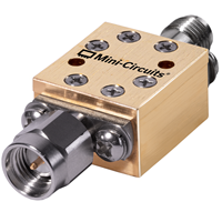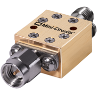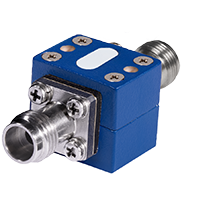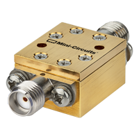

MCDI offers a selection of Mini-Circuits I/Q modulators, I/Q demodulators, QPSK and bi-phase modulation components for RF communications, radar, instrumentation, signal generation and frequency-conversion applications.
Mini-Circuits I/Q modulator and demodulator solutions cover RF/LO frequencies from 1 MHz to 2 GHz, with I and Q signal bandwidths extending from DC to 5 MHz, depending on model.
Available configurations include surface-mount, connectorized and plug-in products, with solutions optimized for low conversion loss, high carrier rejection, strong sideband rejection, good amplitude and phase balance and suppression of unwanted harmonics.
MCDI’s Application Engineering team in Israel can assist you in selecting the appropriate modulator or demodulator according to RF/LO frequency, I/Q bandwidth, conversion loss, carrier rejection, sideband rejection, amplitude balance, phase balance and application.
Hebrew & English Professional Support
Get a quote within hours or less
DDP & Ex-Works - your choice
Custom Adapters & Catalog modifications
Access to Mini-Circuits full portfolio
Mini-Circuits Quality & Reliability
Use the product catalog below to compare Mini-Circuits modulation and demodulation products according to your application requirements.
For complete operating conditions, drive levels, matching, conversion loss, isolation, rejection, amplitude/phase balance and maximum ratings, always refer to the individual Mini-Circuits product datasheet.
Surface-Mount I/Q Modulators
Compare according to:
Surface-Mount I/Q Demodulators
Compare according to:
Selected Mini-Circuits PIN-diode attenuator/switch products can also be used for bi-phase modulation.
Compare these separately according to:
Selected Mini-Circuits PIN-diode attenuator/switch products can also be used for bi-phase modulation.
Compare these separately according to:
Connectorized & Plug-In I/Q Modulators
Compare according to:
Connectorized & Plug-In I/Q Demodulators
Compare according to:
Selected Mini-Circuits PIN-diode attenuator/switch products can also be used for bi-phase modulation.
Compare these separately according to:
The I and Q components are nominally separated by 90° of phase.
Together, these two signals allow both amplitude and phase information to be represented.
This makes I/Q architectures useful in many communication and signal-generation applications.
An I/Q modulator uses I and Q input signals together with a local oscillator or carrier to create an RF output.
An I/Q demodulator performs the reverse process, using an RF signal and local oscillator to generate separate I and Q output signals.
Quadrature Phase Shift Keying – QPSK is a digital modulation method in which information is represented using four RF phase states.
The nominal phase states are:
Because four different states are available, each QPSK symbol can represent two bits of information.
QPSK is widely used where efficient use of RF bandwidth and robust digital modulation are required.
Applications can include:
RF test equipment
An I/Q modulator combines:
to produce a modulated RF output.
A typical internal architecture uses:
The relative amplitudes and phases of the I and Q inputs determine the amplitude and phase of the resulting RF signal.
This architecture can support:
An I/Q demodulator separates an RF signal into its in-phase and quadrature components.
The RF input is mixed with two local-oscillator signals separated by approximately 90°.
The resulting outputs are:
I/Q demodulation is widely used in:
The I and Q outputs normally require appropriate low-pass filtering to remove unwanted high-frequency mixer products.
A bi-phase modulator provides two primary RF phase states:
0° and 180°
The phase state is changed by controlling the polarity of the modulation signal.
Bi-phase modulation can therefore be used for:
Mini-Circuits offers selected PIN-diode attenuator/switch products that can operate as bi-phase modulators.
These products should be considered separately from full I/Q modulators because their architecture and control requirements are different.
A bi-phase modulator typically provides:
2 phase states: 0° and 180°
A QPSK modulator provides:
4 phase states: 0°, 90°, 180° and 270°
QPSK can therefore encode more information per symbol than simple bi-phase or BPSK modulation.
The correct architecture depends on the modulation method required by the communication or test system.
First confirm that the required carrier or LO frequency falls within the modulator’s specified RF/LO operating range.
Mini-Circuits I/Q and QPSK products cover selected applications from 1 MHz to 2 GHz.
The I and Q ports determine the modulation bandwidth.
Current Mini-Circuits I/Q modulator and demodulator solutions support baseband or I/Q frequencies from DC to as high as 5 MHz, depending on model.
The required I/Q bandwidth depends on:
Conversion loss describes the RF power relationship through the modulation or demodulation process.
Lower conversion loss can help preserve signal level and reduce the gain required elsewhere in the system.
Always evaluate conversion loss across the complete required RF/LO frequency range.
Carrier rejection indicates how effectively residual unmodulated LO or carrier energy is suppressed at the modulator output.
Higher carrier rejection is generally desirable because excessive residual carrier can:
Carrier rejection is normally specified in dBc.
For this parameter, a larger positive dBc number represents better suppression.
An ideal quadrature modulator can suppress one unwanted sideband when the I and Q signals have the correct amplitude and phase relationship.
Sideband rejection indicates how effectively this unwanted sideband is suppressed.
Higher sideband rejection generally means better quadrature accuracy.
Performance depends strongly on:
I/Q and QPSK modulators may also generate harmonics of the I and Q modulation signals.
Mini-Circuits specifies suppression of relevant 3× and 5× I/Q harmonic components for selected products.
Higher harmonic suppression helps produce a cleaner modulated RF spectrum.
The modulator must be driven within the LO/carrier and I/Q signal levels specified in its datasheet.
Incorrect drive levels can degrade:
Always use the individual product datasheet to determine the appropriate drive conditions.
The RF input and LO must both remain within the demodulator’s specified operating range.
Make sure the I/Q outputs support the complete information bandwidth required by the signal.
Amplitude unbalance measures the difference in output level between the I and Q signal paths.
Ideally, both paths should have equal amplitude.
Lower amplitude unbalance generally improves quadrature accuracy.
Ideally, the I and Q outputs are separated by exactly 90°.
Phase unbalance or phase error measures the deviation from the ideal quadrature relationship.
Lower phase error improves:
The I and Q outputs may contain both the desired baseband/IF signal and unwanted high-frequency mixer products.
Appropriate low-pass filtering may therefore be required.
The filter should provide adequate rejection while maintaining suitable:
over the wanted I/Q bandwidth.
An I/Q modulator ideally produces only the desired modulated RF signal.
In practice, some carrier or LO energy may leak directly to the output.
Carrier rejection compares the unwanted residual carrier with the desired signal.
For example:
40 dBc carrier rejection
means the residual carrier is approximately 40 dB below the reference modulated signal level under the specified measurement conditions.
Higher values represent better carrier suppression.
A quadrature modulator can generate upper and lower sidebands.
When configured for single-sideband operation, one sideband is desired and the other should ideally be cancelled.
Sideband rejection measures the effectiveness of that cancellation.
The achievable rejection depends strongly on I/Q amplitude and phase matching.
Even small errors can degrade unwanted-sideband suppression.
Quadrature demodulation can also be used in image-reject receiver architectures.
By processing the I and Q outputs with the correct amplitude and phase relationship, the desired signal can be reinforced while an unwanted image is suppressed.
Performance depends on the complete quadrature signal chain, including:
For broader high-frequency I/Q mixer requirements, also explore Mini-Circuits’ RF Frequency Mixer portfolio.
An I/Q modulator can be used to produce single-sideband – SSB signals when the I and Q inputs are correctly phased and scaled.
The quadrature relationship allows one mixing product to add while the opposite sideband cancels.
This technique can be useful in:
For applications requiring high sideband suppression, carefully control:
I/Q and QPSK architectures are widely used for generating and receiving digitally modulated RF signals.
QPSK modulators generate four discrete RF phase states and can therefore be used in digital radios, telemetry, communications and test systems.
I/Q and bi-phase architectures can be used in radar for:
Quadrature modulation and demodulation are widely used in satellite communication systems for efficient transmission and reception of digital information.
I/Q modulators and demodulators can be used in:
I/Q modulators can suppress one unwanted sideband when driven with correctly phased I and Q signals.
This makes them useful in SSB frequency-conversion systems.
I/Q demodulators can form part of image-reject receiver architectures, allowing quadrature signal processing to distinguish desired and image responses.
An I/Q modulator is closely related to a mixer-based frequency converter but includes quadrature signal paths.
A conventional mixer typically provides one nonlinear conversion path.
An I/Q architecture uses two paths separated by approximately 90°, allowing control of both amplitude and phase.
This enables additional functions including:
For general-purpose frequency translation over much wider microwave and millimeter-wave frequency ranges, use the Mini-Circuits RF Frequency Mixer catalog.
QPSK is one specific form of I/Q-based digital modulation.
The same I and Q representation is also fundamental to more complex modulation formats.
The discrete Mini-Circuits modulators on this page should therefore be selected according to their specified analog/RF performance and should not automatically be treated as complete modern digital modems.
Baseband waveform generation, encoding, decoding and digital signal processing are normally implemented elsewhere in the system.
I/Q means In-Phase and Quadrature.
The two signal components are nominally separated by 90° and together represent the amplitude and phase of an RF signal.
An I/Q modulator combines in-phase and quadrature input signals with an RF carrier or local oscillator to generate a modulated RF output.
An I/Q demodulator converts an RF signal into separate in-phase and quadrature output signals for further filtering or signal processing.
QPSK means Quadrature Phase Shift Keying.
It uses four nominal RF phase states:
0°, 90°, 180° and 270°.
Because QPSK has four possible states, each symbol can represent two bits.
A bi-phase modulator normally switches an RF signal between two phase states approximately 180° apart.
It can be used for BPSK and phase-switching applications.
Bi-phase modulation provides two phase states.
QPSK provides four phase states, allowing two bits of information to be represented by each symbol.
Carrier rejection measures how effectively unwanted residual carrier or LO energy is suppressed at a modulator output.
Higher dBc values represent better carrier suppression.
Sideband rejection measures how effectively the unwanted sideband is suppressed relative to the desired sideband.
It is strongly influenced by I/Q amplitude and phase accuracy.
Amplitude unbalance is the difference in signal amplitude between the I and Q paths.
Lower amplitude unbalance improves quadrature accuracy.
Phase unbalance measures deviation from the ideal 90° phase relationship between the I and Q signal paths.
Lower phase error is generally desirable.
In addition to the desired I/Q signal, the mixer process can produce unwanted higher-frequency products.
Low-pass filtering is normally used to retain the desired baseband or IF information while suppressing these unwanted components.
Yes.
With appropriate I and Q signals having the correct amplitude and 90° phase relationship, an I/Q modulator can suppress one sideband and generate an SSB output.
Yes.
Quadrature demodulation combined with appropriate I/Q signal processing can be used to suppress an unwanted image response.
The current Mini-Circuits Modulators / Demodulators portfolio covers RF/LO frequencies from 1 MHz to 2 GHz, with I/Q frequencies from DC to 5 MHz, depending on product.
Mini-Circuits offers selected surface-mount, connectorized and plug-in modulator / demodulator products.
Yes.
MCDI’s Application Engineering team in Israel can help identify suitable Mini-Circuits modulators or demodulators according to RF/LO frequency, I/Q bandwidth, conversion loss, rejection, balance, modulation architecture and package requirements.
MCDI is Mini-Circuits’ exclusive representative and distributor in Israel, providing Israeli engineers and purchasing teams with access to Mini-Circuits RF products together with local technical, commercial and logistical support.
Local Application Engineering
Selecting a modulator or demodulator requires balancing:
MCDI’s Application Engineers can help evaluate these requirements and identify suitable Mini-Circuits products.
Technical Support in Hebrew and English
Discuss your modulation or demodulation requirements directly with an Israel-based engineering team familiar with Mini-Circuits RF components and complete signal chains.
Complete Signal-Chain Support
MCDI can also assist with related Mini-Circuits products including:
allowing the modulator or demodulator to be evaluated as part of the complete RF architecture.
Special & Custom Solutions
If a catalog product does not meet the required frequency, rejection, balance, package or other performance requirements, contact MCDI to discuss available special or custom Mini-Circuits solutions.
Support from Selection Through Delivery
MCDI supports customers in Israel from product selection and quotation through ordering, logistics and post-sales technical assistance.




Before you leave, you should know that MCDI’s professional team of Application Engineers will be delighted to assist you in sourcing the right component. Just fill the form and we will be back to you shortly.